power circuits between the respective gener-
ator bus and lamp filament.
On SNs 23-003 through 23-084, 24-140 and
subsequent, the landing lights will not illumi-
nate unless the respective landing gear down
and locked switch is closed and provides a
ground. On SNs 23-085 through 24-139, the
landing lights are disabled in flight by the
gear-up trunnion switches.
NOTE
It is recommended that the lights be
operated in the L and R LDG LT po-
sitions as sparingly as possible.
Lamp service life is shortened in the
LDG LT position because of the
higher current flow.
RECOGNITION LIGHTS (NOT
INSTALLED ON ALL
AIRPLANES)
A 250-watt recognition light is installed in the
nose of the right tank or in both tanks (Figure
3-9). The light is controlled with the RECOG
switch. When turned on, DC power, applied
through the RECOG LT circuit breaker, closes
a control relay and connects power through a
30-ampere current limiter to each light.
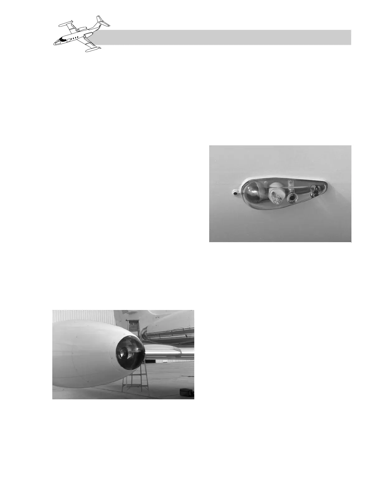
STROBE LIGHTS
The strobe light system consists of one strobe
light mounted inside each wingtip navigation
light fixture (Figure 3-10) and one in the tail,
a power supply for each strobe, a STROBE
switch, a DC STROBE LTS circuit breaker, and
a timing circuit module that causes the strobes
to flash. Each power supply is protected by an
internal 3-ampere fuse.
NAVIGATION LIGHTS
The navigation light system consists of one
lamp in the outboard side of each tip tank
(Figure 3-10), two lamps in the upper aft tail
fairing, a NAV LT switch, and a NAV LTS cir-
cuit breaker on the left main bus.
All three navigation lights are controlled by
the NAV LT switch. Additionally, position-
ing the NAV LT switch on dims the landing
gear safe/unsafe lights and the flight director
annunciator lights.
3-7
FOR TRAINING PURPOSES ONLY