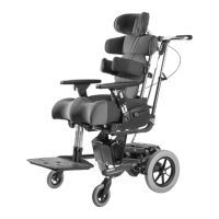
The Leckey BeMe is a Class 1 Medical Device designed as a postural supportive seating system for children with disabilities, facilitating function and mobility. It is intended for use at home, in school environments, or outdoors when paired with an outdoor base. The system is modular and can be used with various indoor or outdoor chassis.
Important Technical Specifications (Metric):
The Leckey BeMe is available in three sizes, with maximum user weights for each component determining the overall system's maximum user weight (the lower of the seat core, backrest, or chassis).
Seat Core and Seats:
- Small:
- Seat Depth: 170*-325 mm
- Seat Width Maximum (No Hip Guides): 275 mm
- Seat Width Maximum (Contoured): 250 mm
- Maximum Weight Limit: 35 kg
- Medium:
- Seat Depth: 275-390 mm
- Seat Width Maximum (No Hip Guides): 325 mm
- Seat Width Maximum (Contoured): 300 mm
- Femoral Width on Split Seat: 90-125 mm
- Maximum Weight Limit: 50 kg
- Large:
- Seat Depth: 350-475 mm
- Seat Width Maximum (No Hip Guides): 415 mm
- Seat Width Maximum (Contoured): 400 mm
- Femoral Width on Split Seat: 110-160 mm
- Maximum Weight Limit: 70 kg
- Medium Long:
- Seat Depth: 325-440 mm
- Seat Width Maximum (No Hip Guides): 325 mm
- Seat Width Maximum (Contoured): 300 mm
- Femoral Width on Split Seat: 90-125 mm
- Maximum Weight Limit: 50 kg
- Large Long:
- Seat Depth: 400-525 mm
- Seat Width Maximum (No Hip Guides): 415 mm
- Seat Width Maximum (Contoured): 400 mm
- Femoral Width on Split Seat: 110-160 mm
- Maximum Weight Limit: 70 kg
Backrest:
- Small:
- Back Height: 360-470 mm
- Back Height with Contoured Seat: 370-480 mm
- Lateral Width: 130-230 mm
- Hip Guide Width: 165-230 mm
- Backrest Angle: +10 to -25 degrees
- Maximum Weight Limit: 35 kg
- Medium:
- Back Height: 390-520 mm
- Back Height with Contoured Seat: 400-530 mm
- Lateral Width: 200-300 mm
- Hip Guide Width: 200-260 mm
- Backrest Angle: +10 to -25 degrees
- Maximum Weight Limit: 50 kg
- Large:
- Back Height: 500-650 mm
- Back Height with Contoured Seat: 475-625 mm
- Lateral Width: 225-350 mm
- Hip Guide Width: 250-350 mm
- Backrest Angle: +10 to -25 degrees
- Maximum Weight Limit: 70 kg
- Small:
- Lower Leg length with Basic/Split Seat: 185-285 mm
- Lower Leg length with Contoured Seat: 185-285 mm
- Maximum Dorsiflexion: +/- 10 degrees
- Maximum Plantarflexion: +/- 10 degrees
- Medium:
- Lower Leg length with Basic/Split Seat: 280-450 mm
- Lower Leg length with Contoured Seat: 290-460 mm
- Maximum Dorsiflexion: +/- 10 degrees
- Maximum Plantarflexion: +/- 10 degrees
- Large:
- Lower Leg length with Basic/Split Seat: 290-510 mm
- Lower Leg length with Contoured Seat: 300-520 mm
- Maximum Dorsiflexion: +/- 10 degrees
- Maximum Plantarflexion: +/- 10 degrees
Chassis:
- Small:
- Footprint Width: 535 mm
- Footprint Length: 635 mm
- Tilt Range: -10 to 30 degrees
- Floor to Seat - Minimum: 270 mm
- Floor to Seat - Maximum: 650 mm
- Maximum Weight Limit: 35 kg
- Medium Ind Gas:
- Footprint Width: 690 mm
- Footprint Length: 840 mm
- Tilt Range: -10 to 25 degrees
- Floor to Seat - Minimum: 340 mm
- Floor to Seat - Maximum: 655 mm
- Maximum Weight Limit: 50 kg
- Medium Ind Hydraulic:
- Footprint Width: 690 mm
- Footprint Length: 840 mm
- Tilt Range: -10 to 25 degrees
- Floor to Seat - Minimum: 325 mm
- Floor to Seat - Maximum: 615 mm
- Maximum Weight Limit: 50 kg
- Medium Ind/Out:
- Footprint Width: 740 mm
- Footprint Length: 880 mm
- Tilt Range: -10 to 25 degrees
- Floor to Seat - Minimum: 380 mm
- Floor to Seat - Maximum: 670 mm
- Maximum Weight Limit: 50 kg
- Large Hydraulic:
- Footprint Width: 800 mm
- Footprint Length: 770/850 mm (including Foot Pedal)
- Tilt Range: -10 to 30 degrees
- Floor to Seat - Minimum: 460 mm
- Floor to Seat - Maximum: 640 mm
- Maximum Weight Limit: 70 kg
- Large Power:
- Footprint Width: 800 mm
- Footprint Length: 770 mm
- Tilt Range: -10 to 30 degrees
- Floor to Seat - Minimum: 460 mm
- Floor to Seat - Maximum: 640 mm
- Maximum Weight Limit: 70 kg
Electrical Specifications (for Powered High-Low Chassis):
- Actuator: LINAK 281209-01
- Battery: LINAK BA18021-00
- Hand Controller: LINAK HB41000-00004
- Battery Charger: LINAK Battery Charger CH01 (only use supplied charger)
- Seat lift operation Duty Cycle: Maximum 10% or 2 min continuous followed by 18 min not in use
- Actuator Force: 3500N push, 2000N pull
- Actuator operating speed: 4.7mm/sec at full load
- Noise level: 48 dB(A)
- IP Rating: IP51 (not waterproof, clean with a damp cloth only)
- Operation Temperature: +5 deg C to 40 deg C
- Transport and Storage Temperature: -10 deg C to 50 deg C
- Humidity (non-condensing): 20% to 80% RH
- Height above sea level: Max 3000m
- Actuator operating voltage: 24V
- Actuator operating current: Maximum 3.9A
- Charger input: 100 – 240 Vac, 50/60 Hz
- Charger output: 27.6 Vdc ± 2%
- Charging current: Max 500 mA
- Charging indication on charger: Green LED – Mains power; Yellow LED – Charging, turns to Green when battery fully charged
- EMC Certification: IEC60601-1-2:2014 for home use environment
- Electrical Safety Certification: IEC60601-1:2005/A1:2012
Usage Features:
- Transferring Child: The seat can be adjusted to a comfortable angle for transfer. Castors should be locked and facing outwards for stability. Pelvic belts/cradles and sandal straps should be unclipped/opened.
- Flip Away Laterals: Operated by pulling a pin, these allow for easier transfers. Flexible wraparound laterals can be flexed outwards and secured with elastic straps.
- 4-Point and 2-Point Belts: These belts attach by passing webbing through slots in the seat moulding and cam buckles, then pulling taut. Padding should face the child. The pelvic strap must always be attached first. For 2-point belts, webbing must be fed through the slot in the seat core (not over it).
- Pelvic Cradle Adjustment: Tightened or loosened using grey webbing at the front and flip-down locks at the side for comfort and stability.
- Chassis Height Adjustment (Gas Spring): The height adjustment pedal is locked with a pull pin. To adjust, unlock the pin, press the foot lever at the rear of the chassis while holding the push handle. The seat fixes at the chosen height when the foot is removed. The safety pin should be re-engaged.
- Chassis Height Adjustment (Hydraulic - Pump Action): To raise, pump the foot pedal. To lower, lift the pedal up with your foot.
- Chassis Height Adjustment (Electric): Adjusted with a push-button control handset. Takes approximately 17 seconds to travel the full range (260mm). The battery should be fully charged for 12 hours before first use and topped up daily for about one hour. The electrical seat height can be operated while charging.
- Tilt-in-Space (Small High-Low Chassis): To unlock, pull out and twist the locking pin, then press the lever. Always hold the seat or push handle to prevent sudden movement. The tilt-in-space lever should be kept locked when not in use. Only use on level ground; for slopes/ramps, ensure the seat back is upright and height is lowest.
- Tilt-in-Space (Medium High-Low Chassis): To adjust, press the lever under the seat base. To lock, twist the pull pin to the right side of the lever.
- Tilt-in-Space (Large High-Low Chassis): To adjust, pull the lever on the push handles.
- Dynamic Backrest Resistance: Adjusted by varying air pressure using an air pump on the main air valve. Pressure range is 50-250psi; do not exceed 250psi.
- Dynamic Backrest Speed: Adjusted by rotating a red wheel on the dynamic shock. Clockwise decreases speed, anti-clockwise increases speed.
- Setting Dynamic Backrest to "Firm": Toggle the blue lever on the dynamic shock to the 'lock' position. This setting is required for transportation.
- Butterfly Harness Adjustment: Webbing length can be adjusted through cam buckles at the back of the seat base or top of the backrest, or on the harness straps.
- Attaching/Detaching Tray: Ensure cam levers on armrests are open before inserting tray tubes. Secure by tightening cam levers. Do not place objects hotter than 40°C (104°F) on the tray, or objects heavier than 8kg (17.6lbs). Never use the tray to steer or push the chair.
- Adjusting Tray Angle: Locate the cam lever in the armrest, raise to unlock, adjust angle, then lower to lock.
- Adjusting Armrest Angle: Locate the cam lever in the armrest, raise to unlock, adjust angle, then lower to lock.
- Operating Flip Away Footplate: Pull the plunger outwards to release, rotate upwards, and release the plunger to lock. Individual footplates rotate upwards without a locking mechanism.
- Adjusting Sandals: Secure feet with Velcro straps over the bridge of the foot and toes. Adjust sandal position on the footplate by loosening and tightening a knob.
- Adjusting Ankle Wraps: Adjust Velcro straps around the bridge of the foot and ankle.
- Adjusting Ankle Huggers: Adjust Velcro strap around the ankle and the length of the strap through the triglide.
- Applying Brakes (Indoor Chassis): Apply pressure to the brake pedal until a click is heard. Tap the top of the pedal to release.
- Applying Brakes (Indoor/Outdoor or Large High-Low Chassis): Push down on the push-pull manual brake lever at the front of the back wheel. Pull up to release. No front wheel brakes.
- Adjusting Height of Push Handle: Loosen locking levers, raise or lower, then tighten.
- Attaching/Detaching Pommel: Open cam lock, place bracket through seat cushion opening into receiver slot. Push down firmly on cam lock. Orientate with thinner edge facing child. Tighten screw in cam lever if loose. Always remove before placing child in seat.
- Attaching/Detaching Femoral Guides: Slot stem into receiver, press downwards until self-locked. To detach, slide silver release button diagonally upwards and pull out.
- Attaching/Detaching Backrest: Open receiver lock paddles by pulling horizontally outwards and rotating upwards. Place backrest base into receiver, rotate paddles downwards, and push inwards to secure.
- Attaching/Detaching Extendable Push Handle (Small and Medium Chassis High-Low Only): Insert lower stems into receiving tubes, pressing safety poppers. Secure by tightening locking bolts.
- Attaching/Detaching Femoral Bars: Secure hardware into front curved slots on underside of seat base. Ensure split washer is between plane washer and bolt head. Place locking plate between moulding and nut. Orientate locking plate with short edge forward. Insert femoral bar into cavity, ensuring locking plate is retained. Secure with countersunk screw and nut.
- Attaching/Detaching Leg Stem: Loosen clamp, slot round boss of upper leg stem into clamp, re-tighten. Adjust femoral bar position if needed by loosening bolt on underside of seat base.
- Attaching/Detaching Basic, Split and Contoured Seat Hardware: Locate downward pointing prongs at front of seat plate and upper slot in receivers. Slot prongs into receivers, aligning holes. Tighten with 4 bolts.
- Attaching/Detaching Contoured Seat: Align front of seat base platework with front of contoured seat foam. Press down to secure Velcro.
- Attaching/Detaching Basic Backrest Foam: Locate holes, place washer on screw, pass through foam and platework. Secure with nut using a spanner.
- Attaching/Detaching Basic Backrest Cover: Slide top of cover over backrest, secure with snap fasteners. Tuck stretch fabric between foam and platework. Slide bottom of cover underneath and secure with snap fasteners.
- Attaching/Detaching Sacral Cover: Align cover with moulding, secure with snap fasteners at sides and underneath.
- Attaching/Detaching Thoracic Backrest Cover: Slot top of sacral cover into cavity on underside of thoracic cover. Align thoracic cover with moulding, secure with snap fasteners at top and bottom.
- Attaching/Detaching Shoulder Section Cover: Slot top of thoracic cover into cavity on underside of shoulder cover. Align with moulding, wrap over ends, secure with zips. Ensure cut-outs align with harness connectors.
- Attaching/Detaching Rain Canopy: Remove existing backrest tube by loosening bolts of height adjustment clamp, raising tube, pressing poppers, and lifting. Slide shoulder pad clamp onto rain canopy backrest tube and secure. Place ends of backrest tube into receivers of height clamp, press poppers, push down, tighten bolts. Slide canopy connectors over receiver, rotate clip inwards to snap.
- Attaching/Detaching Padded Tray Cover: Remove tray. Undo Velcro straps, slot cover over plastic tray. Overlap Velcro straps on underside.
- Attaching/Detaching Elbow Blocker: Remove tray, washers, and bolts. Position bracket so pad rests on top surface of tray, align holes. Reattach bolts and washers.
- Attaching/Detaching Universal Headrest Bracket: Loosen bolt to open clamp. Place clamp over top bar of backrest, centralise. Clamp together by accessing bolt head through hole, engaging threads of nut.
- Attaching/Detaching Universal Headrest: Place sleeve into receiving bracket. Slide stem into sleeve, secure with hand lever.
- Attaching/Detaching Whitmyer Headrest: Slide stem into receiving bracket, secure with hand lever.
- Attaching/Detaching Shoulder Wing Upgrade (Moderate Backrest Only): Remove shoulder blank moulding by unscrewing 3 screws. Replace with shoulder wing upgrade, ensuring bolt head points upwards. Secure with 3 screws.
- Attaching/Detaching Shoulder Angle Spacer (Moderate Backrest Only): Remove cushion cover and 4 screws to separate moulding from clamp. Place back plate pacer onto front surface of clamp moulding. Secure spacer with 4 longer screws. Reattach shoulder moulding by tightening screws into spacer.
Clinical Setup for Postural Management:
- Adjusting Seat Depth on Basic Seat: Loosen left and right bolts on underside of seat base, move forward/backward, tighten.
- Adjusting Seat Depth and Leg Angle (Abduction and Adduction) on Split Seat: Loosen left and right bolts on underside of seat base, move each leg component separately (forward, backward, up to 15 degrees abduction/adduction), tighten.
- Adjusting Seat Depth on Contoured Seat: Remove cushion assembly, covers, and foam. Loosen bolts at either side of plate, slide forward/backward, tighten.
- Adjusting Hip Width on Contoured Seat: Reposition hip pads on Velcro base, aligning dashed lines and back edge of pads with platework.
- Adjusting Hip Pad Width on Basic and Split Seat (Basic Backrest): Release snap fastener of backrest cushion to access adjustment bolt. Loosen bolt, adjust inward/outward, tighten.
- Adjusting Hip Pad Width on Basic and Split Seat (Moderate and Complex Backrest): Locate adjustment bolt at back of moulding. Loosen bolt, adjust inward/outward, tighten.
- Adjusting Hip Pad Height and Angle: Remove two bolts, reset into adjacent hole combinations. Move nuts into corresponding recesses. Hip pad assemblies can be swapped left-to-right for additional height. Loosen two bolts to adjust angle, tighten.
- Adjusting Height of Backrest: Loosen bolts of height adjustment clamp, raise/lower telescoping tubes. To lower from highest position, press snap fastener and push downwards. Tighten bolts.
- Adjusting Height of Individual Pads on Moderate and Complex Backrests: Loosen bolts of basic or complex clamp, slide clamp up/down tubes, tighten.
- Adjusting Depth of Sacral Section (Moderate and Complex Only): Loosen bolt at either side of clamp. Adjust depth by moving backrest section forwards/backwards, tighten.
- Adjusting Angle of Sacral Section (Moderate and Complex Only): Loosen bolts of clamp. Adjust angle by rotating backrest section in all axes, tighten.
- Adjusting Depth of Middle Backrest Section (Complex Only): Loosen bolt at either side of clamp. Adjust depth by moving backrest section forwards/backwards, tighten.
- Adjusting Angle of Middle Backrest Section (Complex Only): Loosen bolts of clamp. Adjust angle by rotating backrest section in all axes, tighten.
- Adjusting Depth of Shoulder Section (Complex Only): Loosen bolt at either side of clamp. Adjust depth by moving backrest section forwards/backwards, tighten.
- Adjusting Angle of Shoulder Section (Complex Only): Loosen bolts of clamp. Adjust angle by rotating backrest section in all axes, tighten.
- Adjusting Footrest Length: Loosen bolt, lengthen/shorten footrest, tighten. For individual footrests, adjust independently. For one-piece, loosen bolts simultaneously.
- Adjusting Foot Stem Angle (Knee Angle): Loosen bolt, rotate foot stem, tighten. For two-piece footrests, adjust independently. For one-piece, loosen bolts simultaneously.
- Adjusting Footrest Angle (Dorsiflexion and Plantarflexion): For two-piece footplate, loosen/tighten hand knob underneath. For one-piece footplate, loosen/tighten bolt on top surface.
- Adjusting Sandals: Loosen knob, move to desired position, tighten.
- Adjusting Ankle Huggers: Adjust Velcro strap around ankle and length of strap through triglide.
- Adjusting Ankle Wraps: Adjust Velcro straps around bridge of foot and ankle.
- Adjusting Booties: Adjust Velcro strap around bridge of foot, Velcro strap around ankle, and length of strap through triglide.
- Adjusting Laterals (Width, Height and Angle): Loosen bolt at back of basic or moderate/complex backrest. Adjust height, width, and angle, tighten.
- Adjusting Laterals (Depth): Open Velcro of cover to access adjustment bolt. Loosen bolt, adjust forward/backward, tighten. Reattach Velcro cover.
- Adjusting Flexible Wraparound Hugging Laterals: Adjust tension by adjusting webbing length on front lateral strap.
- Adjusting Armrest Height: Loosen bolt (off-centre from midline), slide bolt across to other side of midline to allow height adjustment. Slide bolt back to original off-centre position into desired height position, tighten.
- Adjusting Armrest Angle: Locate cam lever in armrest centre. Raise to unlock, change angle, lower to lock.
- Adjusting Armrest Depth: Remove bolts to separate PU pad from platework. Reposition pad in one of three positions, insert bolts, tighten.
- Adjusting Headrest: Loosen bolts. Adjust height, depth, and angle, tighten.
- Adjusting Headrest Lateral Angle: Unzip cover to access adjustment bolt. Loosen bolt, move lateral, tighten.
- Adjusting Tray Angle: Locate cam lever in armrest centre. Raise to unlock, change angle, lower to lock.
- Adjusting Elbow Blocker Positioning: Loosen bolts, slide pad along slots, tighten.
- Adjusting 4-Point Belt: Pass grey webbing through upper slot in seat moulding, then through cam buckle. Pass black webbing through front cam buckle. Pull taut, secure cam buckles. Ensure padding faces child.
- Adjusting 2-Point Belt: Pass grey webbing through upper slot in seat moulding, then through cam buckle. Pull taut, secure cam buckles. Ensure padding faces child.
- Adjusting Pelvic Cradle: Change amount of webbing passing through cam buckles at side of seat base or back of seat. Adjust length of webbing on front straps.
Maintenance Features:
- Daily Checks: Check for lateral movement/wobble in moving parts, ensure adjustment knobs/bolts are secure. Check upholstery and Velcro for wear. Check castors move freely and lock securely. Ensure seat unit is fixed to chassis and reclining back locking levers are engaged. Ensure pelvic belt is secured.
- Annual Inspection: Detailed inspection by a technically competent person. Check all ratchet handles, knobs, nuts, bolts, plastic buckles, head support locking bolts, backrest height/angle adjustment bolts, seat depth adjustment bolts, pelvic belt/hip guide attachments, footrest height/angle adjustment. Check high-low chassis height adjustment mechanism. Check tilt-in-space locking lever. Check seat-chassis join for wear. Lift base to check castors, remove dirt, check brakes. Visually check frame weld points for fatigue/cracking.
- Cleaning: Regularly clean with warm water and non-abrasive detergent. Do not use organic solvents or dry-cleaning fluids. Upholstery covers are removable and machine washable at 60°C (low spin, tumble dry low). Remove foam from basic backrest and seat cushions before washing. Other soft upholstery can be washed intact after removing fastenings. Stretch fabric is impermeable to liquid for 30 minutes. Metal and plastic components can be cleaned with soap and water or antibacterial spray. Do not use running water on chassis or electric seat lift system. Ensure product is dry before use.
- Re-issuing Products: Conduct equipment compatibility check for new user. Perform detailed technical inspection. Clean thoroughly. Supply a copy of the user manual.
- Servicing: All servicing and repairs of electronic components on powered high-low chassis must be carried out by Leckey-authorised personnel.
- Disposal: Dispose of seating system in a community waste disposal site. Electrical components must be removed for separate disposal.
- Storage: Store in a dry place not subjected to extreme temperatures. Allow 2 hours to acclimatise to ambient temperature after storage, wipe off condensed moisture.
Warnings and Cautions:
- Toppling Hazard: Using high-low chassis and seat at extreme positions reduces stability. On level ground, use maximum height/recline. On slopes/ramps (up to 10 degrees), ensure seat back is upright and height is lowest.
- Finger Trap Hazard: Take care with raising/lowering mechanism of powered high-low chassis.
- Occupant Security: Ensure 2-point belt webbing is fed through the slot above the camlock. Fasten and adjust all harnesses, especially pelvic belts, before moving or leaving the seat. Dynamic backrest must be set to "firm" during transportation.
- Finger Pinch Hazard: Take care when assembling or adjusting seat components.
- Daily Checks: Perform daily checks as outlined in Section 11.
- Trip Hazard with Powered Chassis: Disconnect battery charging cable before moving the seat.
- Cleaning Power Washers/Hoses: Do not use hoses or power washers on frame components; electric seat lift system is not sealed against running water.
- Servicing/Repair of Electronic Components: No user-serviceable components. Repairs by Leckey-authorised personnel only.
- Disposal: Dispose of in community waste disposal site; electrical components separately.
- Bringing into Use: Allow 2 hours to acclimatise from storage, wipe off moisture.
- Unattended Use: Do not leave users unattended.
- Approved Components: Only use Leckey approved components; never modify the product.
- Product Failure: Cease use and contact Customer Care if in doubt or if parts fail.
- Positional Adjustments: Carry out and securely fasten all adjustments before placing user. Keep tools out of reach of children.
- Pelvic Belt First: Always secure the pelvic belt first when placing user in seat.
- Stationary Use: Lock all castors and face them outwards for stability, especially with tilt-in-space or back recline.
- High-Low Chassis Safety: Ensure height adjustment pedal and tilt-in-space lever are locked off.
- Uneven Surfaces: Do not move users over uneven surfaces on High-Low chassis.
- Steering: Only use push handle to steer; never use tray or headrest.
- Choking Hazard: Product contains small components. Check locking knobs and bolts are tightened.
- Fire Safety: Complies with EN12182. Keep away from direct heat sources.
- Tray Temperature: Do not place objects hotter than 40°C (104°F) on the tray.
- Storage Conditions: Store in a dry place, +5°C to +40°C (41°F to 104°F).
- Push Handle Security: Check plastic hand knobs are tightened and push handle is secured with two button head screws.
- Seat Core Engagement: Always check seat core is fully engaged with chassis.
- Tray Finger Trap: Be aware of gap on underside of tray where fingers could get trapped.
- Tilt-in-Space Jerking: Hold handlebars or secure seat to prevent jerking.
- Crash Test: Leckey BeMe is crash tested to ISO16840 part 4. Must be forward facing, used with Unwin Restraint System and head support during transport.
- Medical Device Combinations: Information on compatible combinations available at www.leckey.com.
- Dynamic Backrest Pressure: Pressure range 50-250psi; never exceed 250psi.
- Pelvic Strap First: Always attach pelvic strap first before other adjustments.
- Sandal Straps: Check webbing does not irritate skin if child is wearing sandals or light footwear.
- Armrest/Tray Finger Trap: Use caution to ensure hands/arms are not trapped when inserting tray.
- Pommel Removal: Always remove pommel before placing child in seat.
Contraindications:
There are no contraindications associated with the Leckey BeMe product. Precautions for use with fixed spinal deformities, severe muscle contractures, severe muscular/skeletal asymmetry, progressive/muscle wasting conditions, high risk/recent history of bone fractures, high risk of pressure related injury/open sores, strong uncontrolled movement patterns, poorly controlled seizure activity, dependence on percutaneous endoscopic gastrostomy, medical instability (respiratory/cardiovascular), dependence on 3rd party life-sustaining apparatus (oxygen tanks), or significant learning disabilities/behavioral issues are at the discretion of the prescribing clinician. A trained and experienced clinician should be present during initial assessment, setup, configurations, and re-issues.