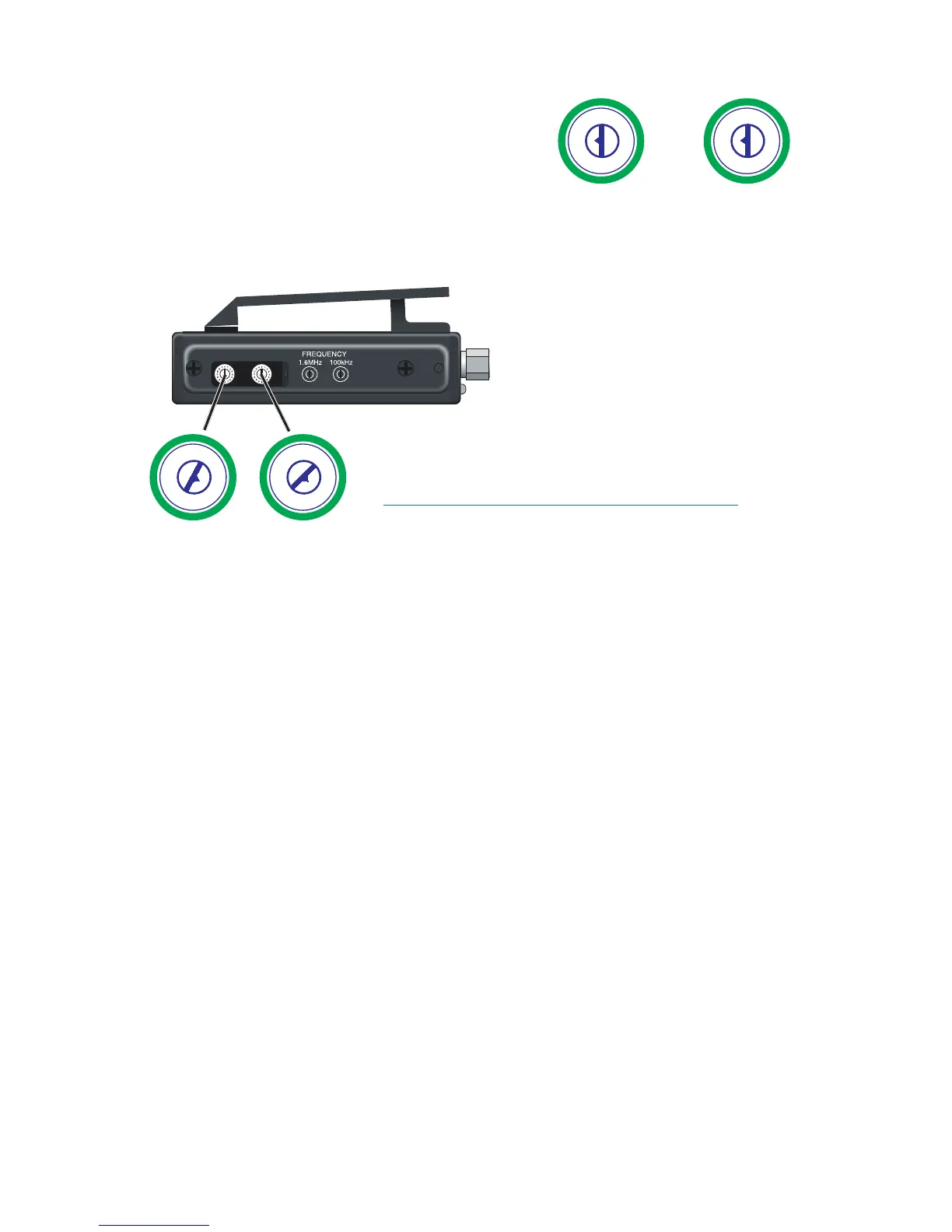
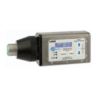
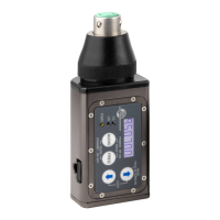
Frequency Select Switches
Two 16-position rotary switches adjust the
center frequency of the carrier. The 1.6M
is a coarse adjustment and the 100K is the
fine adjustment.
Changing the Frequency
Locate the two small rotary switches. (On the UM400a/UM450, slide open
the small door on the side of the transmitter.) With the small screwdriver
supplied with the kit, turn the left
switch to the first character in the
two-digit Transmitter Frequency
Switch Setting code, then turn the
right switch to the second character
of the two-digit code. For example:
the frequency display is 623.000,
and two-digit Transmitter Frequency
Switch Setting code is 56, thus the lefthand switch
on your transmitter should be set to “5” and the
righthand switch to “6”.
Note: Be sure to orient the transmitter so the
nomenclature reads correctly (not upside down).
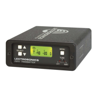
If you are using a receiver with a frequency scan function, find a clear fre-
quency with the receiver, then set the transmitter to match. With Lectrosonics
400 Series receivers, a front panel LCD character display will indicate the
correct transmitter switch settings as a two-character alphanumeric hex code
once a clear frequency has been located with the scan function.