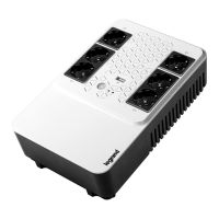
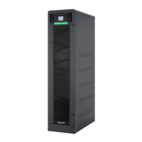
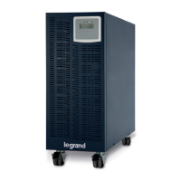
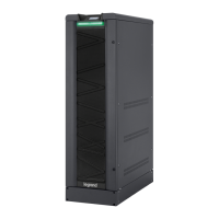
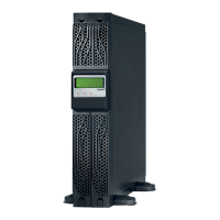
Keor MOD
Installation and maintenance manual
99
TABLE 4
Maximum current absorbed by the batteries at full load and minimum wire cross sections recommended for con-
necting the UPS to the external battery units
POWER MAXIMUM BATTERY CURRENT MINIMUM WIRE CROSS SECTION
125 kVA 5 x 65 A 5 x 16 mm
2
250 kVA 5 x 130 A 5 x 35 mm
2
TABLE 5
External battery cabinets
ITEM CODE
CABINET
DIMENSION
L X D X H mm
SWITCHES AND PROTECTION KIT
BATTERIES
(Ah)
3 109 65 1200 x 900 x 1900 1x FUSE HOLDER 3P NH2 400A - 3x aR FUSE 315A 70-93
3 109 67 1200 x 900 x 1900 1x FUSE HOLDER 3P NH2 400A - 3x aR FUSE 350A 105
3 109 44 1200 x 900 x 1900 1x FUSE HOLDER 3P NH1 250A - 3x aR FUSE 250A 55
3 109 89
2 cabinets
810 x 840 x 1900
2 cabinets
2x FUSE HOLDER 3P NH2 400A - 3x gR FUSE 315A
80

 Loading...


