82
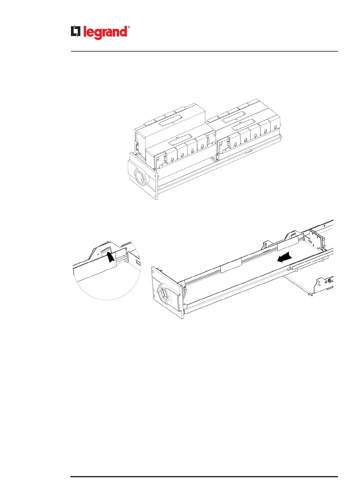
3. Remove all the battery blocks from the drawer
4. Push up the safety hook located on the left side of the battery drawer to unlock the block and pull the drawer to fina-
lize the extraction.
5. Follow the procedure shown at paragraph 4.4 to insert a new battery drawer
6. Follow the procedure described in paragraph 6.3.2.3 to exit from the maintenance bypass mode.
To add a battery drawer:
1. Follow the procedure described in paragraph 6.3.2.1 for setting the UPS in maintenance bypass mode.
2. Follow the procedure shown at paragraph 4.4 to add a new battery drawer
3. Follow the procedure described in paragraph 6.3.2.3 to exit from the maintenance bypass mode.
INDICATION
During the installation/replacement operations, the load is not protected by the UPS because it is powered from the
bypass input line.
6.5 Replacing the fuses and surge arrester (DIN rail)
A surge arrester and two fuse holders can be found in the DIN rail inside the cabinet.
The first fuse holder contains a 16A GG 10x38mm fuse (LG-013316). It is in series to the surge arrester.
The second fuse holder contains a 2A GG 10x38mm fuse (LG-013302). It is in series to the input bypass disconnector
release coil.
The surge arrester is a T2 40kA 1P SPD (LG-412230).
INDICATION
It is mandatory to verify monthly the indication on the surge arrester. The device works correctly if the indicator is green.
If the device is damaged, the indicator is red and the surge arrester must be replaced.
6. Maintenance

 Loading...