Group 5 Transport/Start up Page 55
Release R2.0 LEIBINGER JET3
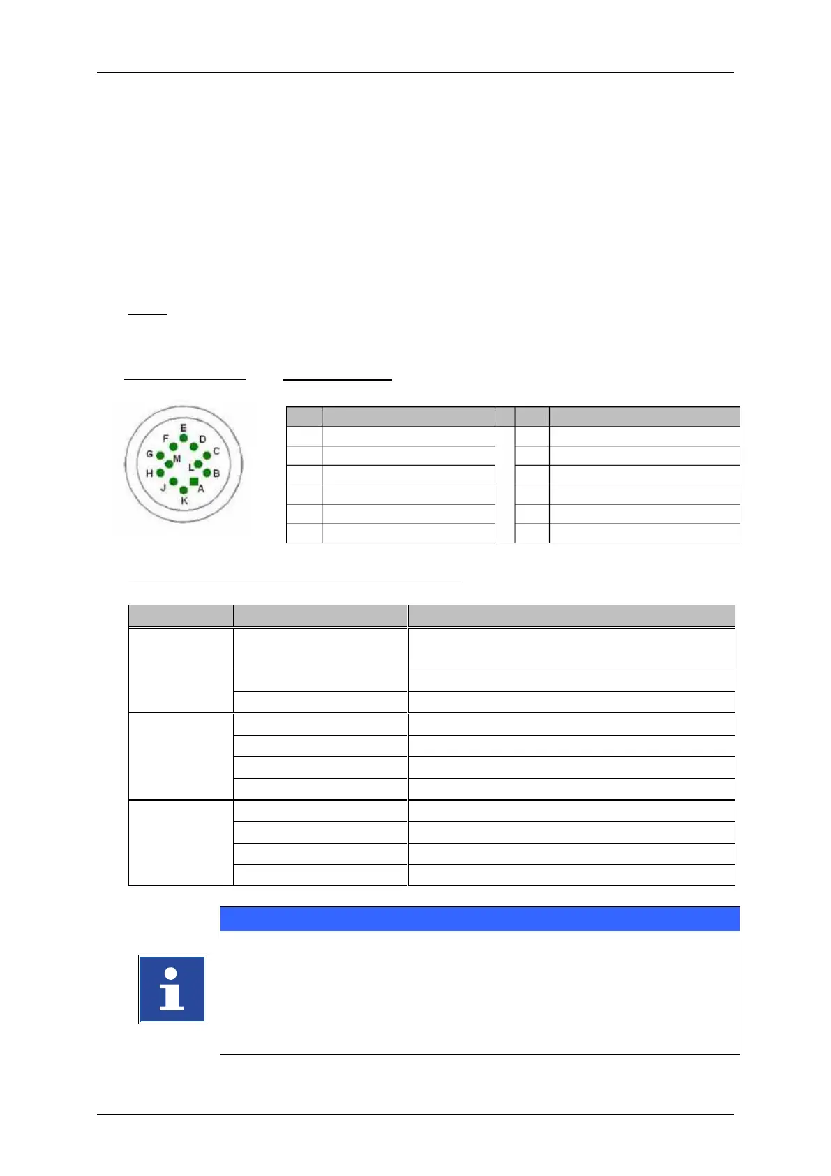
5.5.3 Interface X1 (Encoder)
5.5.3.1 Description and configuration
The interface “X1” provides the connection of a shaft encoder.
Due to the input for which you can set the software individually, the encoders can be
connected according to different norms without an additional converter.
Note: For variable product speed you have to use a shaft encoder to synchronize the
printing speed or to control the constant font width.
Basic data /Recommended working conditions:
Difference input +/-200mV
Input voltage range: -0,3 bis 5,5V
The signal type which should be used as encoder source has to be set
in the software of the JET3 under Settings Basic Settings Encoder
Interface.
You will find a circuit diagram of the interface in the manual appendix!
(1)
All 24V inputs which are designated with (1) are protected by a self-reset fuse with 700 mA.
 Loading...