Group 5 Transport/Start up Page 54
Release R2.0 LEIBINGER JET3
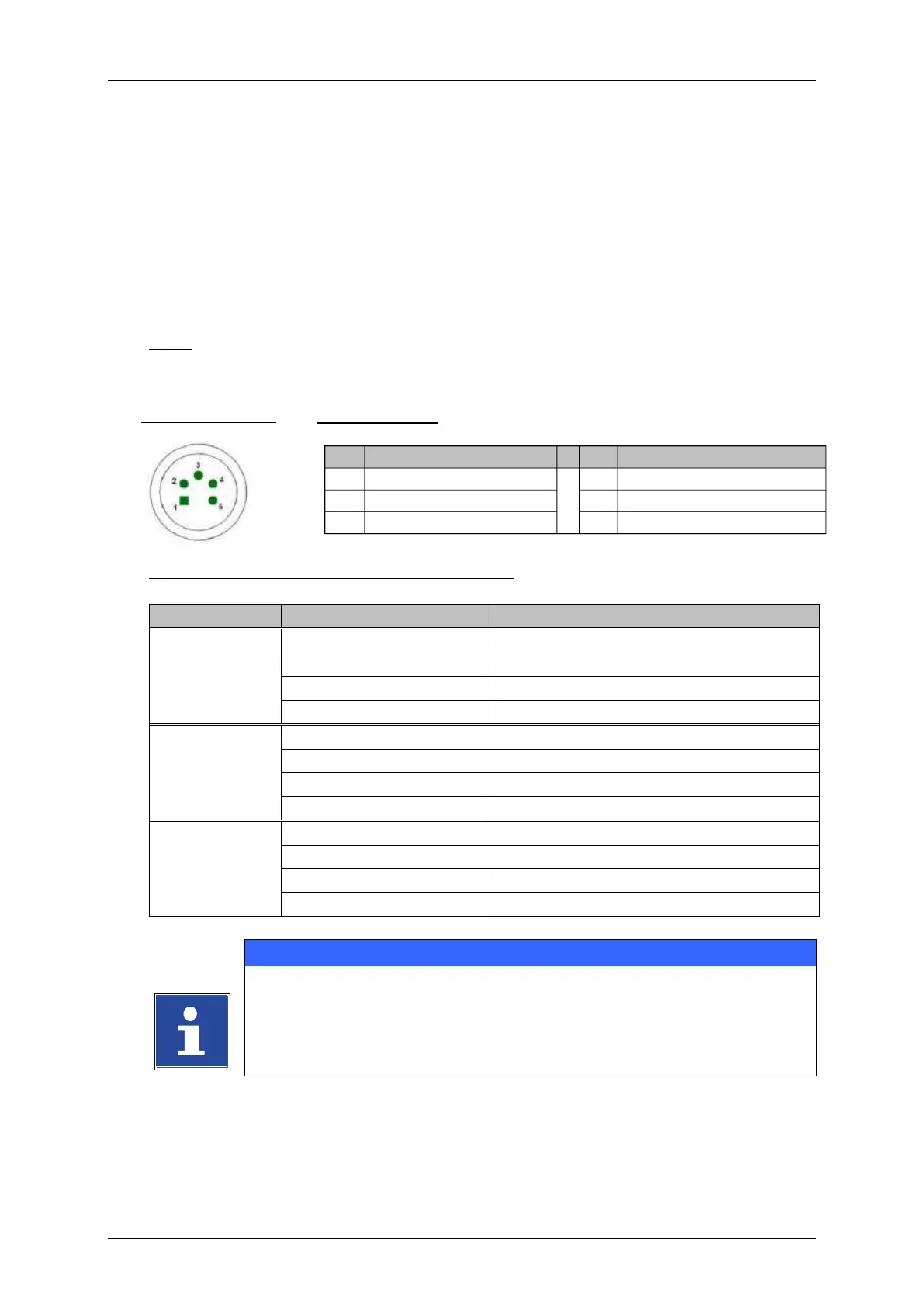
5.5.2 Interface X5 (PrintGo)
The interface “X5” provides the connection of an external PrintGo-signal. All common
product detectors (e.g. light barrier, product sensor ect.), 24V NPN- as well as 24V
PNP-switching can be connected.
Regarding the software you can select additionally if the positive edge or the negative
edge should be used for the release of the print out.
Note: To inform the JET3 when a print text should be printed, you require a so-called
Print-Go signal.
Basic data/Recommended working conditions:
-3,5V up to 3,5V (or high resistance)
20 up to 28V (or high resistance)
-3,5V up to 3,5V (or high resistance)
You will find a circuit diagram of the interface in the appendix of this
manual!
(1)
All 24V inputs which are designated with (1) are protected by a self-reset fuse with 700 mA.