Group 6 Operation – Optional equipment Page 89
Release R2.0 LEIBINGER JET3
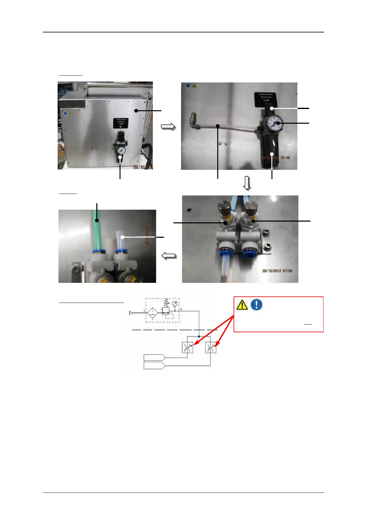
Both of the throttle valves are
adjusted exactly and may not be
adjusted!
Assembly of the external print head ventilation
Outside
Inside
Connection diagram:
1 – rear panel of the housing
2 – pressure regulator valve
4 – Throttle valve for the head ventilation
5 – Throttle valve for the housing ventil.
6 – Hose for the print head ventilation
2.3 – Condensate container (cartridge)
7 – Hose for the housing ventilation