Do you have a question about the Leica SR530 and is the answer not in the manual?
This document outlines the procedure for connecting a Leica SR530 GPS Rover to a SpiderNet, NTRIP, or VRS network using Carlson SurvCE and Carlson TCP Relay software. The primary function of this setup is to enable the SR530 rover to receive real-time kinematic (RTK) corrections from a reference network, facilitating high-precision GPS measurements. This is particularly relevant for users whose reference network requires a GGA position message to be sent from the rover.
The initial setup involves a one-time configuration using the Leica TR500 ("Red Tongue") controller. This controller is essential for setting up the communication parameters on the SR530. Once these parameters are configured and saved, the TR500 controller is no longer needed unless the SR530's system memory is cleared, which would necessitate re-configuration. This design ensures that the field operation is streamlined, reducing the amount of equipment required for daily use.
The process begins by connecting the TR500 controller to the SR530 and powering on the system. Users navigate through the SR530's menu using the keypad, specifically accessing the "CONFIG" and "Interfaces" options. The critical step here is to ensure that "1 Real-Time" is selected and edited to configure the device settings. Within the device settings, "RS232" must be highlighted and edited. A potential conflict warning might appear if the device is already in use by another port; users should proceed by confirming "OK".
A crucial part of this initial configuration is noting the baud rate, parity, data bits, and stop bits displayed on the screen. These communication parameters (typically 9600, None, 8, 1) are vital for correctly setting up TCP Relay later, as they dictate how corrections are sent to the GPS receiver. After noting these settings, users continue through the menus, eventually reaching the "REF" option. Here, "Ref Service" must be set to "VRS" using the Enter and arrow keys. It is equally important to set "Send User ID" to "NO," as TCP Relay will handle this function, and a conflict would arise if it were enabled on the SR530. Once these settings are confirmed, the user returns to the Main Menu and powers off the SR530, detaching the TR500 controller.
The next phase involves the WinCE data collector. This device must be connected to the Internet and possess two viable RS232 ports. Specific cables are required for connecting the data collector to the SR530: one from the SR530's Terminal port to COM1 on the CE device (cable 560254 recommended) and another from Port 1 of the SR530 to COM2 on the CE device (cable 563809, potentially paired with a null-modem and gender changer, or cable 733280 – GEV 160).
With the physical connections established, the software configuration begins. SurvCE and TCP Relay must be installed and registered on the CE device. Upon launching SurvCE, users navigate to the "Equip" tab, select "GPS Rover," and specify "Leica" as the manufacturer and "Leica SR530" as the model. Under the "Comms" tab, the connection type is set to "Cable," Port to "COM 1," Baud to "9600," Parity to "None," Data Bits to "8," and Stop Bits to "1." Pressing the green checkbox initiates communication with the SR530 and powers it on.
Further configuration within SurvCE involves going to the "Utilities" tab from the "Leica GPS Rover Setup" screen and setting the "Radio Type" to "GPRS/NTRIP Connection." Other parameters will gray out and are not used by SurvCE, so they can be ignored. After accepting this setting, users should go to "Equip/Monitor/Skyplot" to verify that SurvCE is communicating with the SR530 and displaying a valid latitude/longitude position. This initial position is crucial for the first GGA message sent to the network.
Once SurvCE is properly configured and communicating, the application is minimized by selecting the SurvCE icon and choosing "Minimize." Carlson TCP Relay is then launched. Within TCP Relay, users select their connection type and enter only the necessary parameters for their specific network, as not all networks require every parameter. A "Friendly Name" can be entered and saved, or the green checkbox can be pressed if parameters are already saved. No information needs to be entered under "Info1" or "Info2," as these are for user reference only and do not impact TCP Relay's performance. Users continue through the screens until they reach the port settings and the "Start Relay" button.
The final critical step in TCP Relay is setting the Port to "COM2," Baud Rate to "9600," Parity to "None," Data Bits to "8," and Stop Bits to "1." Pressing "Start Relay" initiates the connection. If the user has not chosen to automatically minimize TCP Relay, status messages will appear, indicating that GPUID and GGA messages have been sent (if applicable). This screen allows users to monitor their connection to the network. After verifying the connection, TCP Relay is minimized, and the user returns to SurvCE. At this point, the system should be receiving corrections, and the status should transition from "Autonomous" to "Fixed," indicating a successful RTK connection.
The document implicitly highlights a key maintenance feature: the one-time configuration with the TR500 controller. This means that under normal operating conditions, the TR500 is not required for daily field work, simplifying the equipment load and reducing potential points of failure during routine surveys. The configuration settings are stored on the SR530, ensuring persistence across power cycles. The TR500 only becomes necessary again if the SR530's system memory is cleared, which would typically occur during a factory reset or specific troubleshooting scenarios. This design minimizes the need for frequent re-configuration, enhancing operational efficiency.
The reliance on standard RS232 ports and widely available cables (like 560254, 563809, or 733280) for connecting the SR530 to the WinCE data collector ensures that replacement parts are generally accessible. The clear instructions for setting baud rates, parity, data bits, and stop bits in both the SR530 and TCP Relay facilitate troubleshooting communication issues. If corrections are not being received, users can systematically check these parameters in both the hardware and software configurations to identify and resolve discrepancies. The ability to monitor connection status in TCP Relay provides immediate feedback on the health of the network connection, allowing users to quickly diagnose whether the issue lies with the network, the software, or the communication settings. The transition from "Autonomous" to "Fixed" status in SurvCE serves as a clear indicator of successful RTK operation, providing a simple visual check for the user.
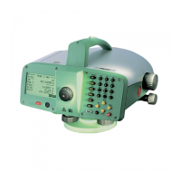
| Type | Total Station |
|---|---|
| Operating Temperature | -20°C to +50°C |
| Angle accuracy | 1" |
| Distance range with single prism | 3500 m |
| Accuracy (horizontal) | 1" |
| Accuracy (vertical) | 1" |
| Data Output | RS-232 |
| Power Supply | Rechargeable battery |