9
Chapter 2Frame Mortise & Tenon Jig User Guide
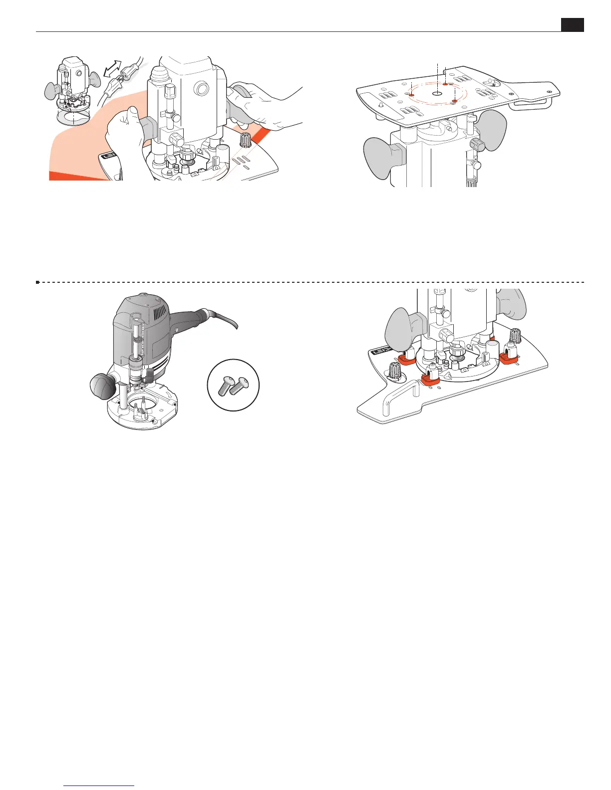
MOUNTING THE ROUTER
2-32 Unplug the router. Remove the router’s plastic Sub-Base (except
Festool 1400) and template guidebush adaptor from 7529 or 8529.
Remove the clear plastic dust cover from 8529 router base top (screw
holes are used to attach Leigh FMT Pro Sub Base). Store removed parts
for future use. Fit the correct shank sized centering mandrel to collet.
With the Leigh Sub-Base on a flat bench corner, place router on top
and plunge mandrel through to bench and lock the plunge.
2-33 Remove the router and stand it upside down on the bench.
Depending on the router design, you may need to support it in
a soft-padded vise. Place the Sub-Base upside down onto the
router’s metal base with the mandrel centering the router to the
base through the bit hole. Rotate the Sub-Base until the correct
threaded screw holes in the router base align with the counter-
bored holes in the Sub-Base.
2-34 Festool 1400 series routers attach using the two No. 5130 screws
provided, through base holes No. 11. Festool 2200 series routers attach
using the two No. 5130 screws in the No. 12 holes.
5130
2-35 m In addition to the base screws it is vital to attach the four
U-Posts and four of the shim stops (either size) and position and
tighten these against the edge of the router base to prevent lateral
router movement. Note: You do not use the fence rods. For correct
positioning, see 2-16 through 2-18, 2-24 and 2-25. Note: Porter
Cable 7529 and 8529 handles will be slightly angled (not parallel)
to the FMT Pro Sub-Base.
■