24
Chapter 4 Frame Mortise & Tenon Jig User Guide
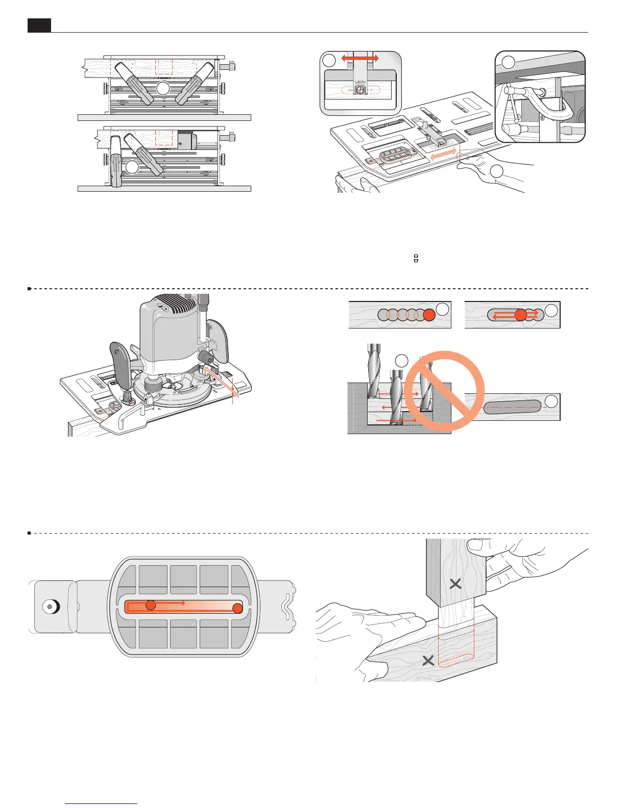
4-15 Remove the router and tenon workpiece from the jig. Position
the two clamps so the mortise piece can be positioned for secure holding.
Clamp to either both sides of the vacuum box
➀
or to one side
➁
.
Note: Leaving a “horn” on the ends of mortise pieces as in
➀
not only
makes for easy clamping, it’s good woodworking practice as the horns
will be an aid in assembly gluing and clamping later.
1
2
4-16 Extend the sight. With the marked side of the mortise piece
toward the clamp plate, either move the board left and right
➀
to align the cross with the sight and clamp in place; or clamp in
place first and move the table to align the sight
➁
. Remember,
you previously set the
limit stops to allow only left/right
movement. For routing very small pieces
➂
, see 3-16.
1
2
4-17
Place the router/Sub-Base assembly on the jig, the left
hand guide pin in the mortise slot part of the guide. Now raise
the plunge stop rod slightly, say
1
⁄32-
1
⁄16"[1-1,5mm] to allow the
mortise to be routed slightly deeper than the tenon to ensure
perfect tenon shoulder flushness on the finished joint.
4-18 The best way to rout mortises (parallel to workpiece) is
plunge full depth, slightly overlapping holes
➀
, then clean out
left-right-left at full depth of cut
➁
. Do not rout left-right-left at
progressively greater depths without plunging holes
➂
… the bit’s
rotation will pull the bit off the intended mortise line with each
pass
➃
and the mortise may not be parallel to the workpiece.
1
4
2
3
4-19 Make sure the guide pin is run clockwise against both the
front and rear of the mortise guide slot on the final passes. The
gap between pin and mortise guide slot is greatly exaggerated in
this illustration.
4-20 Remove the mortise piece and test the tenon for fit and
(keeping the marked faces adjacent) for flushness. If the face sides
are not flush, check the straightness of the two parts. If they are
straight, the clamp plate may not be vertically parallel to the bit.
See Appendix II, Jig Adjustments, A2-1 through A2-3.
MORTISE & TENON ROUTING PROCEDURES