DC-voltage is always measured via a voltage/current transducer.
The connection wires to be used:
Screw terminals:
• Interfaces: 0.14 mm² to 1.5 mm² (use wire end ferrule)
• Measuring and supply terminals: 0.2 mm² to 4 mm² (use wire end ferrules)
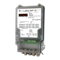
Parallel to the screw terminal for the RS interface there is a plug connector (grid dimension 2.54 mm)
to which a computer/laptop can be connected locally. The plug connector and the screw terminals are
connected to each other electrically. Thus, both interfaces are of the same RS type. When reading out
locally you must make sure that there is currently no communication in process via the RS screw
terminals. An active communication process is indicated in the display by an arrow over "RS". If an
attempt to communicate is made whilst another communication process is in process, the current
communication process breaks down.
Cable glands (properties):
• Measuring signal 3 x M16 x 1.5 (Ø 6.5 – 9.5 mm)
1 x M20 x 1.5 (Ø 9.5 – 13.5 mm)
• Supply and communication 4 x M16 x 1.5 (Ø 4.0 – 6.5 mm)
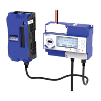
Since the nomenclature of the terminals of the RS422 interface for the LEM Products EM4T and
EM4TII+ are different, please use in case of replacement of the EM4T with EM4TII+ in an installation
the table below to connect the RS422 interface.