T
Theresa DavisAug 4, 2025
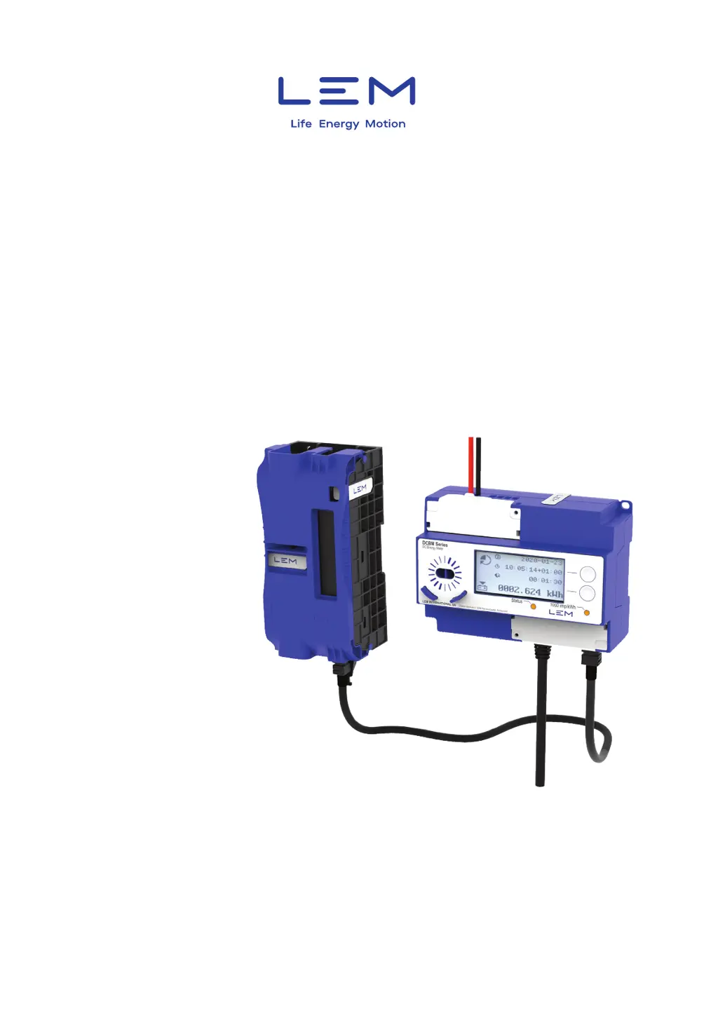
How to reconnect LEM DCBM 400 Measuring Instruments Meter Unit to the Sensor Unit?
- DDonald CaseyAug 4, 2025
If the Meter Unit of your LEM Measuring Instruments is disconnected from the Sensor Unit, follow these steps: 1. Ensure that all connectors are properly inserted on both the Meter Unit and Sensor Unit sides. 2. Verify that the Sensor Unit and Meter Unit are correctly paired, using the markings on them as a guide. 3. Inspect the connectors on the Meter Unit, Sensor Unit, and cable for any dirt or fluid. Check the cable for cuts or signs of excessive mechanical stress. If necessary, try replacing the cable.