Page 33/95
21January2021/Version 0
LEM International SA
Chemin des Aulx 8
1228 PLAN-LES-OUATES Switzerland
www.lem.com
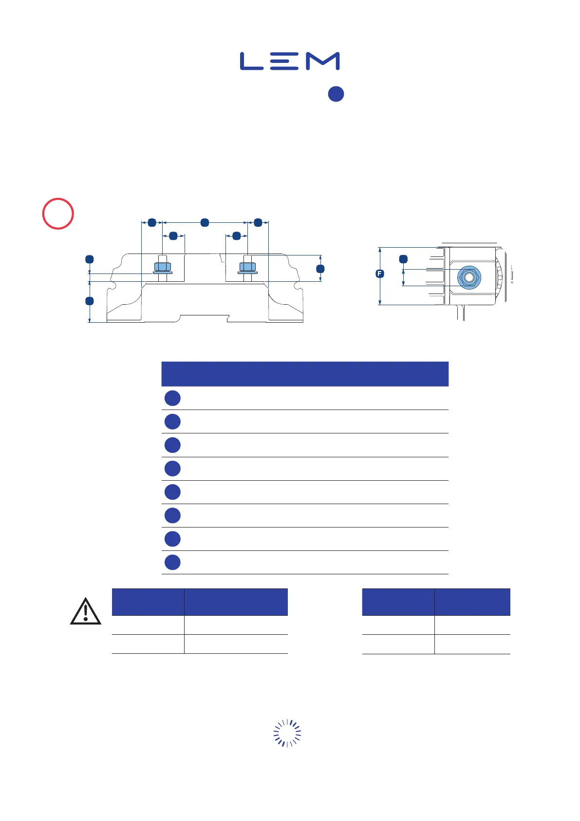
You can connect the product with bus bars and lugs.
F
The product is compatible for one lug per connection conguration with all lugs from standard:
• NF C 20-130: 2004
• DIN 46220: 1965
• DIN 46234: 1980
• DIN 46235: 1983
!
2 lugs can connect on each terminal, not all the lugs are compatible. Please check the dimensions.
A B
HH
E
D
G
C
A
Figure 17: Sensor Unit integration
A
15 mm 15 mm
62 mm 62 mm
19 mm 27 mm
D
30 mm 40 mm
E
9 mm max.
1)
13 mm max.
1)
F
34.6 mm 52.9 mm
G
13 mm 18 mm
H
15.9 mm 15.9 mm
1)
Maximum thickness
for bus bar or lugs
Fire
hazard
DCBM_SU40XX 10.4 ±0.5
DCBM_SU60XX 36.4 ±0.5
⌀
M8 8.5
M12 12.5
Table 2: Torque values for installation Table 3: Bus bar drilling


 To Next Page