Page 22/95
21January2021/Version 0
LEM International SA
Chemin des Aulx 8
1228 PLAN-LES-OUATES Switzerland
www.lem.com
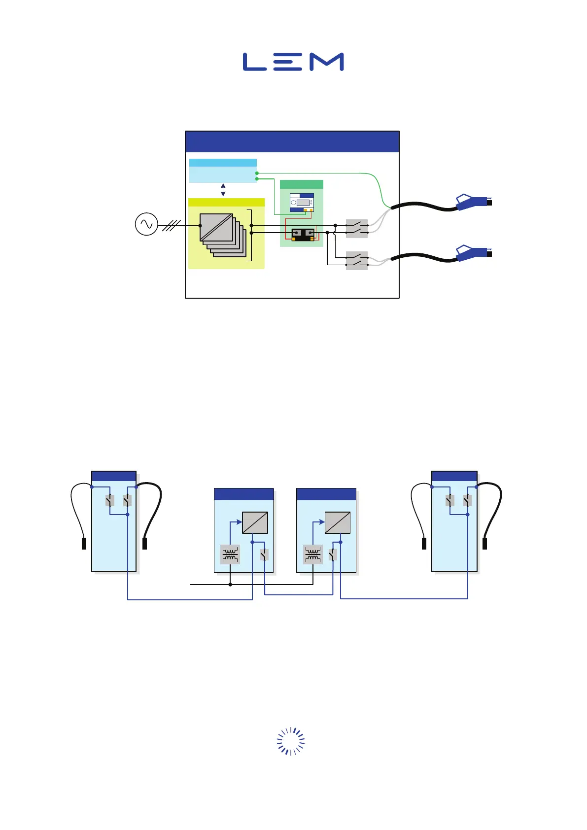
In such application, the DCBM is integrated before the power relays. This integration is preferred
because it optimizes space in the existing 50 kW charging station. Only one output cable can be
supplied at the same time.
Power stacks
AC
DC
Communica�on & Control
Charge Post
Grid
Power stacks
DCBM
CHAdeMO
CCS
Figure 6: DCBM in a typical 50 kW EVSE
To reduce charging time, high power charging is used. Specic power electronic techniques (e.g.
liquid-cooled cables) are used. Currents up to 600 A are applied during charging, with a maximum
system voltage of 1000 V DC.
To optimize system performance, central AC/DC converters are used instead of dedicated
converters in the charge posts (the cabinet to connect the EV). Several DC buses link the central
converters to the charge posts.
DC Bus
DC Bus
175kW Module
AC
DC
AC grid
175kW Module
AC
DC
Charge Post
CCSCHAdeMO
Liquid
cooled
cable
Charge Post
CCSCHAdeMO
Liquid
cooled
cable
Figure 7: Typical 350 kW EVSE system


 To Next Page