Page 44/95
21January2021/Version 0
LEM International SA
Chemin des Aulx 8
1228 PLAN-LES-OUATES Switzerland
www.lem.com
In standard installations, the voltage measurement terminals of the DCBM are connected directly
to the bus bars inside the charging station. The voltage sense wires can be connected after the
power relay if necessary.
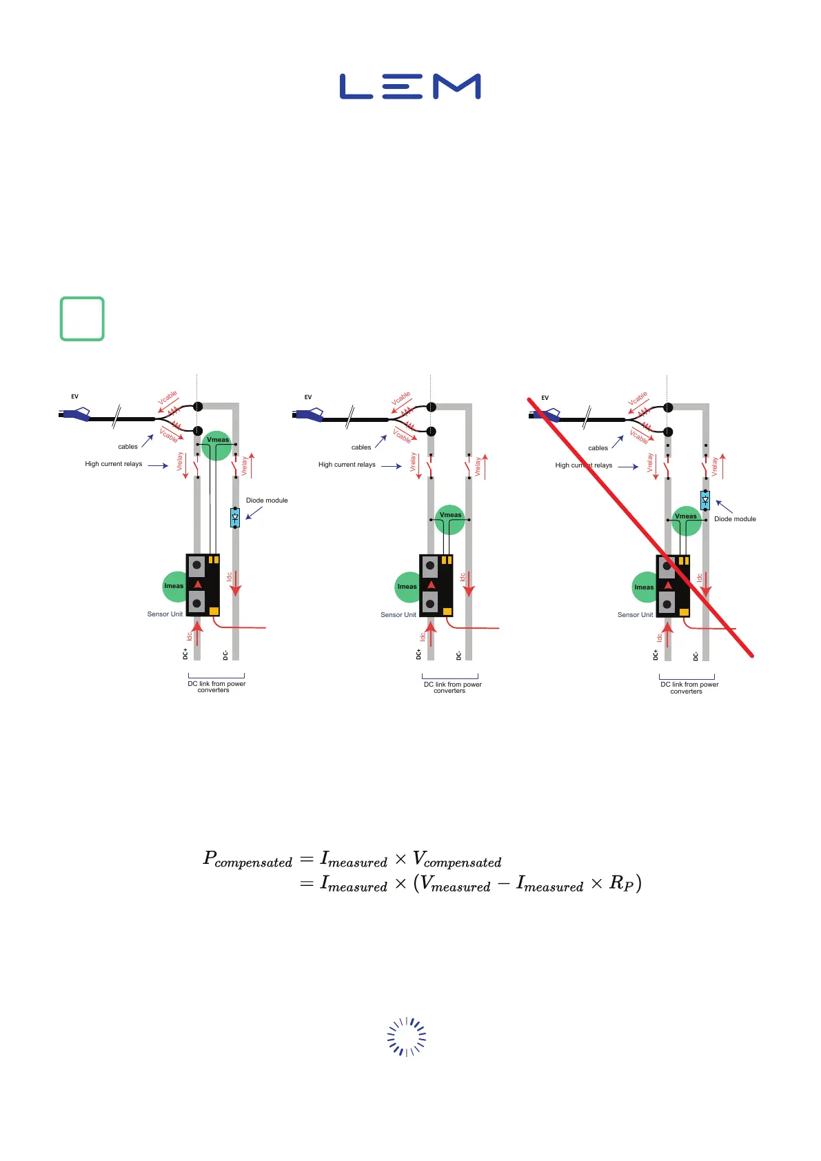
In this case, the cable loss compensation mechanism must be used. Figure hereunder describes
the possible integration.
i
Only resistive losses can be compensated. Notably, power diodes losses cannot be compensated
(i.e. right-hand solution cannot be used).
Figure 26: Integration examples using cable loss compensation
Cable loss compensation consists in subtracting estimated energy losses to actually measured
energy. To do so, the DCBM uses a resistance value, which estimates the dissipation resistance
of the circuit. This resistance value is referred to as R
P
. The compensated energy is integration of
compensated power, calculated as follows:
With: P
compensated
& V
compensated
Compensated power & voltage
I
measured
& V
measured
Measured current & voltage
R
P
Resistive compensation


 To Next Page