12
2d). In any case, the system is fully modular, since it’s
possible to expand the number of units simply linking
the signal from one to the other.
Both POSEIDON models include the DPPM - Digitally
Processed Power Module. The digital processor
integrated in the module is able to handle all the signal
processing needed for the system control and includes
a series of PRESETS with all the parameters
(crossover, EQ, etc.) needed for the most common
applications. The PRESETS can be selected from the
module’s control panel (see DPPM module) and, using
the serial connection to a PC, the system’s main
parameters can be remotely controlled and custom
PRESETS can be saved in the internal memory.
5. Installation, connections and transport
1. Installation
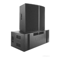
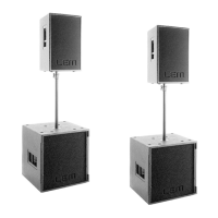
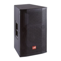
The standard version of POSEIDON 212 is intended for
the on-floor positioning, therefore the units has to be
placed directly on the stage or on appropriate platforms.
If possible, the satellites can also be placed on top of
the subs.
POSEIDON 212 is also available in the FLYING
version, fitted with 4 flying bars on the top and 4 on
the bottom panel. For more details on the POSEIDON
212 FLY and on the optional flying hardware, please
refer to the POSEIDON FLYING MANUAL.
2. Connections
Make use of XLR BALANCED signal cables for the
connection of the enclosures to the mixer (fig. 3).
In a typical satellite/sub configuration, the signal coming
from the mixer can be connected to the first unit and
then linked to the following ones using the SIGNAL
LINK socket (fig. 4).
Additional XLR BALANCED signal cables can be used
to connect all the units through the RS285 serial port
using the RS485 IN and RS485 OUT sockets (fig. 4).
3. Transport
POSEIDON 212 is provided with 2 steel handles for
transport.
POSEIDON 218 has four wheels on the bottom panel
and 4 steel handles on both sides for an easy handling
of the unit.
6. DPPM module - Connection panel (fig. 5)
1. POWERCON socket for the power supply cable.
2. POWERCON for the power supply linking to a
second unit.
3. ON/OFF switch.
4. Balanced XLR-F socket for the input signal con-
nection (+4dB sensitivity).
5. Balanced XLR-M socket for the signal linking to a
second unit.
6. Control for separating the electrical earth from that
of the chassis.
7. 9-pin socket for the connection to the PC RS232
serial port.
8. Balanced XLR-F socket for the RS485 control
signal coming from another unit.
9. Balanced XLR-M socket for the RS485 control
signal linking to another unit.
10. Two-color LED that illuminates when there’s a
signal present at the unit’s input (GREEN color) or
when the internal LIMITER is active (RED color).
11. 2-digit display able to show the current PRESET
number or the built-in processor’s control param-
eters.
12. SEL button for PRESETS, PLUGINS, VOLUME
and COMM menu selection.
13. UP & DOWN button for the parameter setting.
14. ENTER button to be used to confirm the section
of PRESETS or PARAMETERS.
15. LED for the PLUGINS status display.
16. LED for the selected menu indication.
17. Air vents for the module cooling.
WARNING!!!
IN ORDER FOR THE MODULE TO WORK COR-
RECTLY, IT’S VERY IMPORTANT TO KEEP THE AIR
VENTS ALWAYS FREE AND ABLE TO PROVIDE A
PROPER AIR CIRCULATION.
7. Functions and operating procedures
1. DX BOARD - Functions (fig. 6)
The heart of the DPPM module is the DX BOARD, a
digital processing board based on the 40-bit custom
DSP RED 208. The DX BOARD is able to perform all
the processing operations needed for the POSEIDON
system.
- HPF and LPF CROSSOVER filters with the choice
between Butterworth, Bessel or Linkwitz/Riley response
and up to 48 dB/oct. slope;
- 5 EQ filters for the input and 10 EQ filters for each
output, which can be individually set as FULL
PARAMETRIC, HI and LO SHELVING (6 or 12 dB
slope) or NOTCH FILTER;
- DELAY LINES on each input and output for MASTER
DELAY compensation and individual LOUDSPEAKER
alignment;
- PHASE adjustment with 5° step through a full 360°;
- high precision LIMITERS on each output for the
system's loudspeaker protection.