Optional Switches
15
We recommend using 3M 5200 adhesive
caulking to bed the upper mounting
bracket and screws.
DO NOT OVERTIGHTEN.
Attach the actuator to the upper mounting
bracket using the 1-1/2" Delrin Pin
provided.
2) You are now ready to attach the Lenco
Actuator to the blade. First insert the 1-1/4"
Delrin Pin part way through the hole in the
Bennett lower mounting bracket and insert
through one of the four black washers
provided in the kit. Place the actuator
into the bracket and tap the pin through.
Continue through the second washer
and other side of the bracket. Replace
the bracket screw removed in step 3 on
page 14. This will lock the pin in place and
prevent it from falling out.
3) Now you will need to hook up the Lenco
Actuator wires inside the bilge/rigging
area. First cut the wire connector from the
Bennett wire harness where the pump
used to be. Strip the four harness wires and
connect to the four Lenco wires using the
heat shrink butt splices provided in the kit.
Make sure to use the proper crimping tool
and then heat all connections for a tight
waterproof seal. Tie-wrap or secure in some
fashion to a dry location to help prevent the
connectors from getting too wet.
Wiring Instructions For
Connecting Lenco Actuator
Wires to Existing Bennett
Rocker Switch
1) Disconnect all wires from the
Bennett rocker switch. Remove
and discard all brass strips.
Reconnect the four wires from
the existing Bennett wire harness
to the back of the Bennett switch
as per the diagram to the right.
2) Now find a 12 volt negative at the
helm/ console. Connect this to
the 3’ black jumper wire with the
nonterminated end. Attach to screw
terminal on the back of the Bennett
switch as per the diagram to the right
(-12 Volt Black). Attach the orange,
black, yellow, red, green, and blue
short jumper wires to the back of the
Bennett switch as per the diagram
to the right. The 12 volt positive (+)
should already be at the switch
from the previous system. Simply
reconnect it as per the diagram to
the right.
3) Test the trim tabs for proper
operation. Remember that the right
switch controls the left trim tab
and the left controls the right. Bow
down should extend the tabs while
bow up should retract them. If for
some reason this does not work
as described in the above text then
recheck all the wiring for a misplaced
wire. If still not fully operational
refer to the trim tab trouble shooting
guide in the owners manual for
further instructions.
Please follow the instructions and
drawings carefully.
For further assistance please visit our
website at www.lencomarine.com, email
us at info@lencomarine.com, or call us at
772-288-2662
RetroFit Kit for Bennett Trim Tabs Installation Instructions
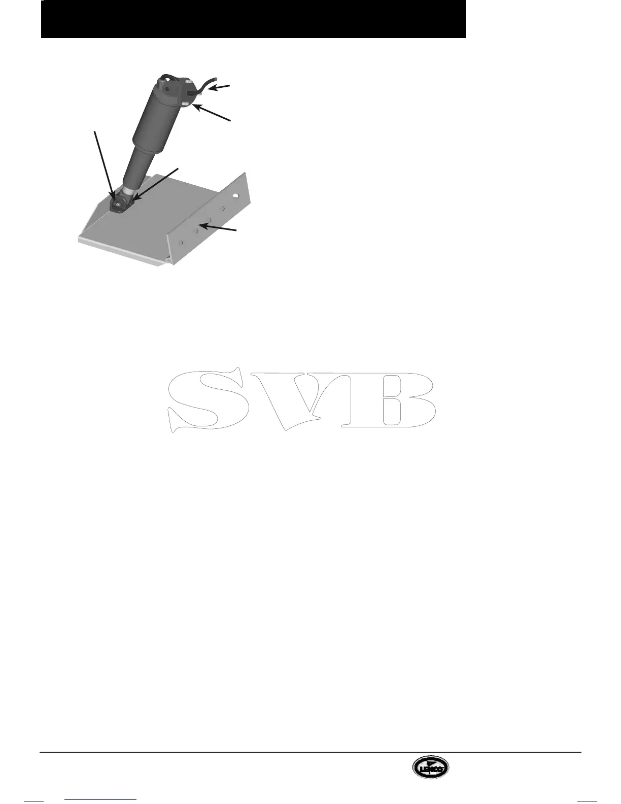
Lenco wire
feeds through
existing oil line
hole in transom
Lenco upper
mounting
bracket fits
existing Bennett
mounting holes
Existing
Bennett
lower
actuator
bracket
Existing
Bennett trim
tab plane and
hinge
Lenco
washers
(One on
each side
of actuator)
 Loading...