Electric RetroFit Kit for Bennett Trim Tabs
Installation Instructions Continued
3) Now you will need to hook up the Lenco
Actuator wires inside the bilge/rigging area.
First cut the wire connector from the Bennett
wire harness where the pump used to be.
Strip the four harness wires, cut the pins on
the four Lenco actuator wires, and strip these
four wires. Connect these wires as per the
diagram below, using the heat shrink butt
splices provided in the kit. Make sure to use
the proper crimping tool and then heat all
connections for a tight waterproof seal.
Tie-wrap or secure in some fashion to a dry
location to help prevent the connectors from
getting too wet.
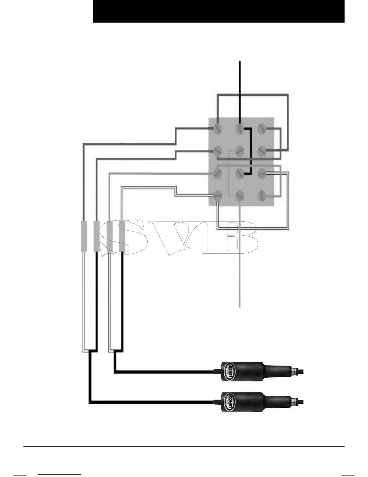
Wiring Instructions For Connecting Lenco
Actuator Wires to Existing Bennett Rocker
Switch
1) Disconnect all wires from the Bennett
rocker switch. Remove and discard all brass
strips. Reconnect the four wires from the
existing Bennett wire harness to the back of
the Bennett switch as per the diagram below.
2) Now find a 12 volt negative at the helm/
Connect this to the 3’ black jumper wire with the non-
terminated end. Attach to screw terminal on the back
of the Bennett switch as per the diagram below (-12
Volt Black). Attach the orange, black, yellow, red,
green, and blue short jumper wires to the back of
the Bennett switch as per the diagram below. The
12 volt positive (+) should already be at the switch
from the previous system. Simply reconnect it as
per the diagram below.
console.
3) Test the trim tabs for proper operation.
that the right switch controls the left trim tab and
the left controls the right. Bow down should extend
the tabs while bow up should retract them. If for
some reason this does not work as described in the
above text then recheck all the wiring for a misplaced
wire. If still not fully operational refer to the trim tab
trouble shooting guide in the owners manual for
further instructions.
Remember