Page 5
1
2
3
4
SUCTION
POCKET
SUCTION
ORBITING SCROLL
STATIONARY SCROLL
SUCTION
SUCTION
DISCHARGE
POCKET
SUCTION
INTERMEDIATE PRESSURE
GAS
CRESCENT
SHAPED
GAS POCKET
HIGH PRESSURE GAS
FLANKS SEALED
BY CENTRIFUGAL
FORCE
MOVEMENT OF ORBIT
FIGURE 6
Due to its efficiency, the scroll compressor is capable of draw
ing a much deeper vacuum than reciprocating compres
sors. Deep vacuum operation can cause internal fusite
arcing resulting in damaged internal parts and will result
in compressor failure. Never use a scroll compressor for
evacuating or to pump system into a vacuum. This type
of damage can be detected and will result in denial of
warranty claims.
The scroll compressor is quieter than a reciprocating com
pressor, however, the two compressors have much different
sound characteristics. The sounds made by a scroll com
pressor do not affect system reliability, performance, or indi
cate damage.
See compressor nameplate or ELECTRICAL DATA for
compressor specifications.
C − Condenser Fan Motor
All units use single−phase PSC fan motors which require a run
capacitor. In all units, the condenser fan is controlled by
the compressor contactor.
ELECTRICAL DATA tables in this manual show specifi
cations for condenser fans used in 13ACCs.
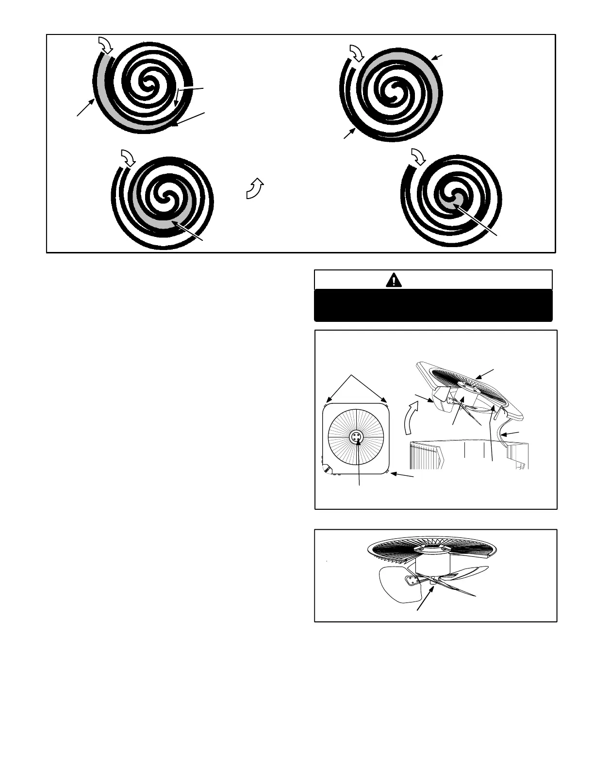
Access to the condenser fan motor on all units is gained
by removing the seven screws securing the fan assem
bly. See figure 7. The condenser fan motor is removed
from the fan guard by removing the four nuts found on
the top panel. Drip loops should be used in wiring when
servicing motor. See figure 8 if condenser fan motor re
placement is necessary.
Make sure all power is disconnected before
beginning electrical service procedures.
DANGER
FAN
CONDENSER FAN MOTOR
AND COMPRESSOR ACCESS
Remove (7) screws
REMOVE (7) SCREWS
SECURING FAN GUARD.
REMOVE FAN GUARD/FAN
ASSEMBLY.
MOTOR
FAN GUARD
WIRING
FIGURE 7
RACEWAY
Remove (4) nuts
ALIGN FAN HUB FLUSH WITH END OF SHAFT
FIGURE 8

 Loading...