Page 6
506374−01 03/10
New Outdoor Unit Placement
See Unit Dimensions on Page 2 for sizing mounting slab,
platforms or supports. Refer to Figure 2 for mandatory
installation clearance requirements.
*
*
*
*
NOTES:
Service panel access clearance of 30 in. (762 mm) must be
maintained.
Clearance to one of the other three sides must be 36 in. (914
mm)
.
Clearance on one of the remaining two sides may be 12 in. (305
mm) and the final side may be 6 in. (152 mm)
.
Clearance required on top of unit is 48 in. (1219 mm).
A clearance of 24 in. (610 mm) must be maintained between two
units.
Figure 2. Installation Clearances
POSITIONING CONSIDERATIONS
CAUTION
In order to avoid injury, take proper precaution when lift-
ing heavy objects.
Consider the following when positioning the unit:
Some localities are adopting sound ordinances based
on the unit’s sound level registered from the adjacent
property, not from the installation property. Install the
unit as far as possible from the property line.
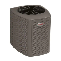
When possible, do not install the unit directly outside
a window. Glass has a very high level of sound
transmission. For proper placement of unit in relation
to a window see the provided illustration in Figure 3.
INSTALL UNIT AWAY
FROM WINDOWS
TWO 90 ELBOWS INSTALLED IN LINE SET
WILL REDUCE LINE SET VIBRATION
Figure 3. Outside Unit Placement
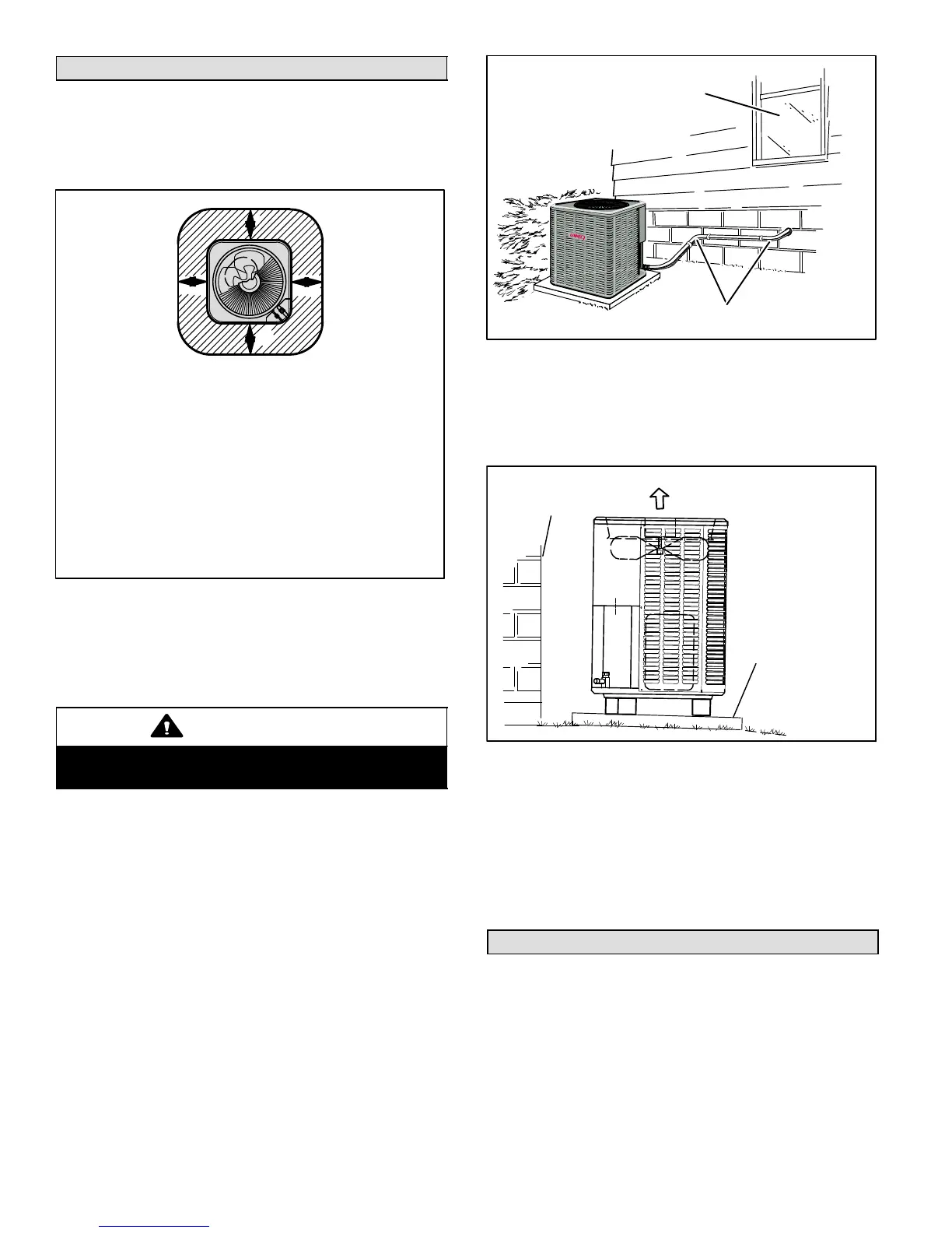
PLACING OUTDOOR UNIT ON SLAB
When installing a unit at grade level, the top of the slab
should be high enough above the grade so that water from
higher ground would not collect around the unit as
illustrated in Figure 4.
GROUND LEVEL
MOUNTING
SLAB
BUILDING
STRUCTURE
DISCHARGE AIR
Figure 4. Typical Slab Mounting at Ground Level
Slab may be level or have a slope tolerance away from the
building of not more than two degrees, or 2 inches per 5
feet (51 mm per 1524 mm) as illustrated in Figure 4.
INSTALLING OUTDOOR UNIT ON ROOF
Install the unit at a minimum of 4 inches (102 mm) above
the surface of the roof. Ensure the weight of the unit is
properly distributed over roof joists and rafters. Redwood
or steel supports are recommended.
New or Replacement Line Set
This section provides information on installation or
replacement of existing line set. If line set is not being
installed or replace then proceed to Brazing Connections
on Page 9.

 Loading...