Page 29
80MGF WITH EGC−2 IGNITION CONTROL
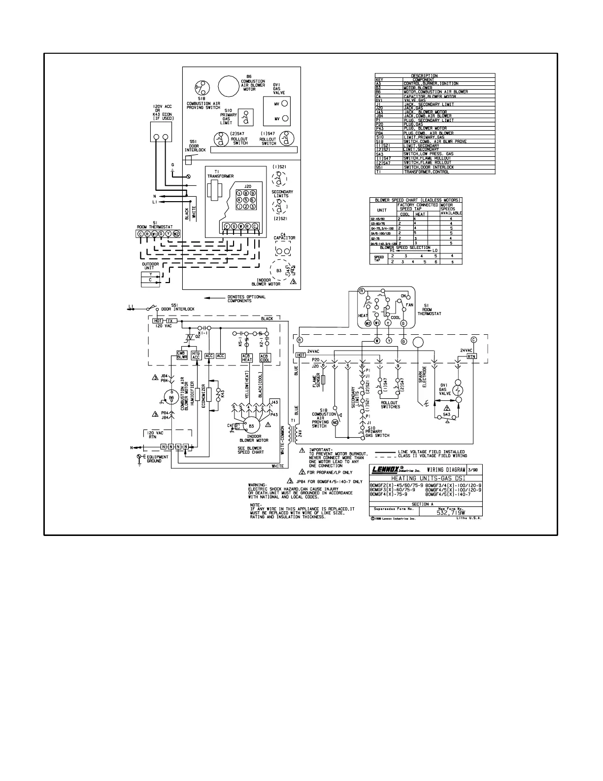
1 − When disconnect is closed, 120V is routed through door
interlock switch (S51) to feed the line voltage side of the
ignition control (A3) and transformer T1 primary. Door in-
terlock switch must be closed for A3 and T1 to receive
voltage.
2 − T1 supplies 24VAC to terminal 24VAC" on A3. In turn,
terminal R" of A3 supplies 24VAC to terminal R" of the
indoor thermostat (not shown).
3 − When there is a call for heat, W1 of the thermostat en-
ergizes W of the ignition control with 24VAC.
4 − CAB of the ignition control energizes the combustion air
blower (B6). When the combustion air blower nears
full speed, combustion air prove switch (S18)
closes.
5 − When S18 closes, assuming primary limit (S10) and
secondary limit (S21) are closed, a 15 second pre−purge
begins. After the pre−purge period the ignition control
starts ignition spark and opens main gas valve.
6 − After 45 seconds, ignition control (A3) energizes the
indoor blower (B3).
7 − When heat demand is satisfied, W1 of the thermostat de-
energizes W of the ignition control and the gas valve is
immediately de-energized. The combustion air blower
immediately stops. The indoor blower runs for a desig-
nated fan off" period (60−240 seconds) as set by jumper
on ignition control.

 Loading...


