Do you have a question about the Lennox 80UHG3-75 and is the answer not in the manual?
Air volume data for various blower speeds and static pressures for specific 80UHG models.
Table showing air resistance in inches of water gauge for various airflow rates.
Information on manifold pressure settings for installations at different altitudes and fuels.
Diagram and identification of key heating components within the furnace unit.
Detailed view and identification of the burner assembly components.
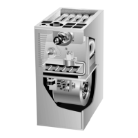
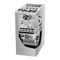
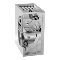
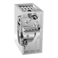
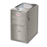
General identification of major unit components and their locations.
Description of the SureLight ignition system for 80UHG-2 and -3 models.
Visual representation of the SureLight control ignition sequence for heating.
Diagram and explanation of the SureLight control board terminals and functions.
Description of the integrated ignition/blower control for 80UHG-1 models.
Information on thermostat wiring and control board connections.
Description of the combustion air inducer motor and its function.
Details on the flame rollout safety switches and their function.
Description of the primary limit control (S10) and its operation.
Description of the secondary limit controls (S21) and their operation.
Details on the spark electrode and flame sensor for 80UHG-1 models.
Description of the gas valve, its types, and safety features.
Explanation of the combustion air blower prove switch (S18) function.
Guidelines for proper unit placement and installation according to codes.
Steps for unit start-up, including preliminary checks and heating start-up.
Procedure for safely turning off the gas supply to the furnace.
Instructions for immediate safety or emergency shutdown of the unit.
Procedure for safely shutting down the unit for extended periods.
Information on unit certification standards for gas appliances.
Requirements and considerations for gas supply piping installation.
Procedure for testing gas piping for leaks and pressure integrity.
Procedure for checking and verifying gas supply pressure.
Procedure for checking and verifying manifold gas pressure.
Method for checking and adjusting gas flow rate for optimal unit operation.
Procedure for measuring the flame signal for ignition control diagnostics.
General information on blower operation and thermostat control.
Procedure for measuring and adjusting the unit's temperature rise.
Procedure for measuring external static pressure using a manometer.
Instructions for selecting blower speed taps on leadless motor models.
Instructions for selecting blower speed taps on leaded motor models.
Guidelines for checking, cleaning, or replacing air filters.
Procedure for cleaning furnace burners and inspecting the heat exchanger.
Instructions for checking and cleaning the supply air blower.
Procedure for checking flue pipe, chimney, and connections for blockages.
Checks for wiring connections, voltage, and blower motor amp-draw.
Wiring diagram for the 80UHG-1 model with SureLight control.
Flowchart detailing the normal and abnormal heating operation sequence.
Flowchart detailing the cooling operation sequence.
Flowchart detailing the continuous fan operation sequence.
Description of the heating sequence for 80UHG-2 models with SureLight control.
Flowchart for normal and abnormal heating sequences.
Continuation of the heating sequence flowchart.
Flowchart for normal and abnormal cooling sequences.
Flowchart for continuous heat speed fan operation.
Guide to diagnose and resolve common unit operational issues using diagnostic codes.
| Model | 80UHG3-75 |
|---|---|
| Type | Gas Furnace |
| Heating Capacity | 75, 000 BTU/hr |
| AFUE Rating | 80% |
| Blower Type | Multi-speed |
| Stages | Single-stage |
| Fuel Type | Natural Gas |
| Blower Motor Type | PSC |
| Ignition Type | Hot Surface Ignition |
| Vent Diameter | 4 inches |






 Loading...