Page 14
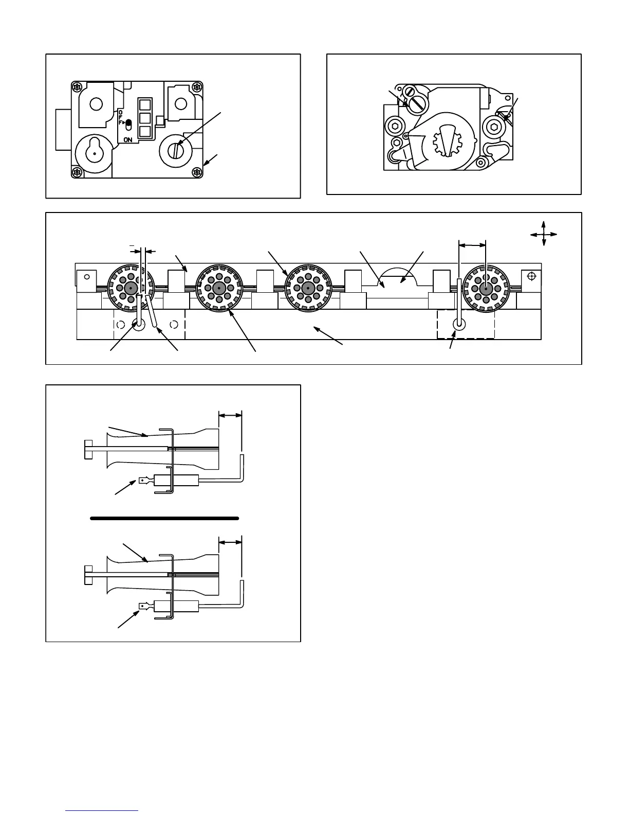
WHITE RODGERS 36E SERIES GAS VALVE
GAS VALVE SHOWN IN OFF POSITION
MANIFOLD
PRESSURE
ADJUSTMENT
SCREW
MANIFOLD
PRESSURE
OUTLET
FIGURE 15
ON
OFF
HONEYWELL VR8205 SERIES GAS VALVE
GAS VALVE SHOWN IN OFF POSITION
MANIFOLD
PRESSURE
ADJUSTMENT
SCREW
MANIFOLD
PRESSURE
OUTLET
FIGURE 16
FIGURE 17
TYPICAL BURNER/ELECTRODE ORIENTATION
BURNER
FLAME RETENTION RING
UPPER BURNER
MOUNTING RAIL
LOWER BURNER
MOUNTING RAIL
MANIFOLD ORIFICE
Right Left
Top
Bottom
FLAME SENSOR
SPARK ELECTRODE
GROUND
1/8"(+1/64")
23/32 in.
(18 mm)
80UHG-1 MODEL SHOWN
FIGURE 18
SPARK ELECTRODE
SPARK ELECTRODE TO BURNER GAP
80UHG-1 MODEL SHOWN
BURNER
FLAME SENSOR TO BURNER GAP
BURNER
FLAME SENSOR
SPARK
ELECTRODE
5/16 in.
(7 mm)
5/16 in.
(7 mm)
13-Combustion Air Blower Prove
Switch (S18)
80UHG series units are equipped with a combustion air
prove switch located on the vestibule panel. The switch is
connected to the combustion air inducer housing by means
of a flexible silicone hose. It monitors air pressure in the
combustion air blower housing.
The switch is a singleĆpole singleĆthrow pressure switch
electrically connected to the furnace control. The purpose
of the switch is to prevent burner operation if the combusĆ
tion air blower is not operating or if the flue becomes obĆ
structed.
 Loading...


