Page 16
IV-HEATING SYSTEM SERVICE CHECKS
A-A.G.A./C.G.A. Certification
All units are A.G.A. and or C.G.A. design certified without
modifications. Refer to the 80UHG Operation and InstallaĆ
tion Instruction Manual Information.
B-Gas Piping
Gas supply piping should not allow more than 0.5"W.C.
drop in pressure between gas meter and unit. Supply
gas pipe must not be smaller than unit gas connection.
Compounds used on gas piping threaded joints should be
resistant to action of liquefied petroleum gases.
C-Testing Gas Piping
IMPORTANT
In case emergency shutdown is required, turn off
the main shutĆoff valve and disconnect the main
power to unit. These controls should be properly
labeled by the installer.
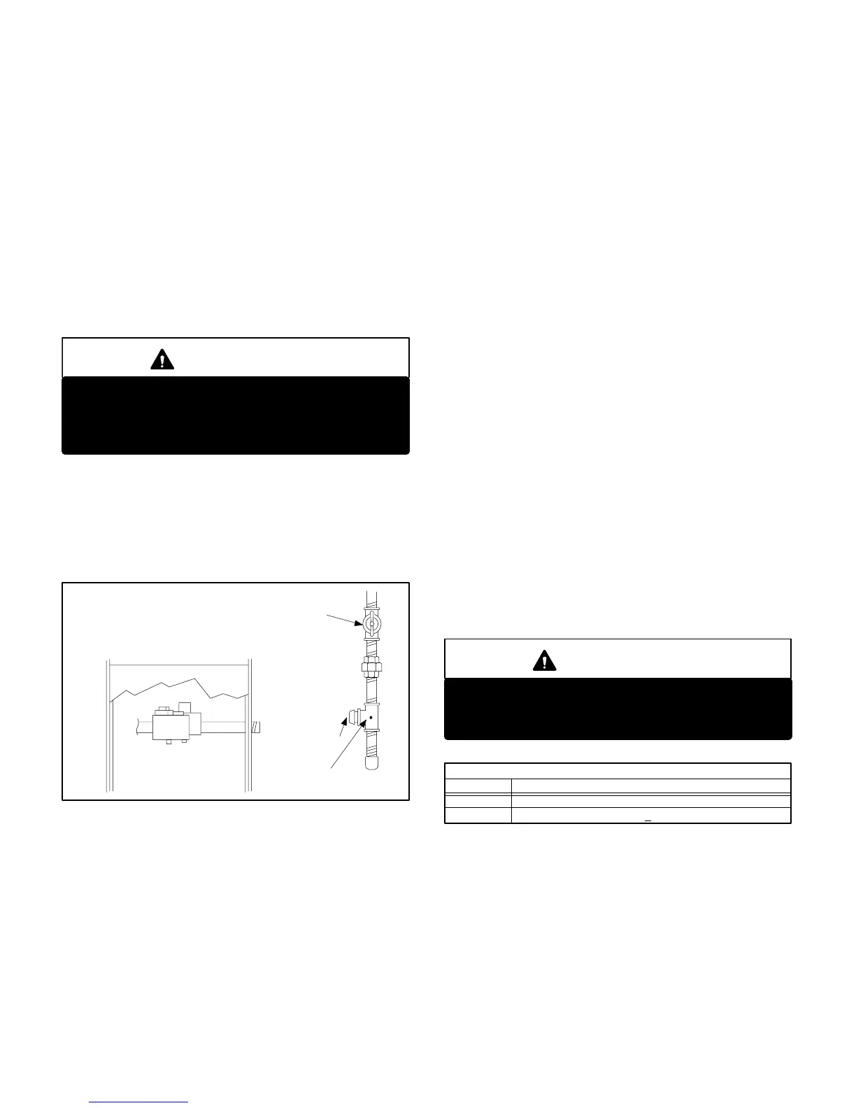
When pressure testing gas lines, the gas valve must be
disconnected and isolated. Gas valves can be damaged if
subjected to more than 0.5psig (14" W.C.). See figure 20. If
the pressure is equal to or less than 0.5psig (14"W.C.), use
the manual shut-off valve before pressure testing to isoĆ
late furnace from gas supply.
FIGURE 20
MANUAL MAIN SHUT-OFF VALVE
WILL NOT HOLD TEST PRESSURE
IN EXCESS OF 0.5 PSIG (14"W.C.)
GAS VALVE
CAP
GAS PIPING TEST PROCEDURE
FIELD PROVIDED
LINE PRESSURE TAP
When checking piping connections for gas leaks, use preĆ
ferred means. Kitchen detergents can cause harmful corroĆ
sion on various metals used in gas piping. Use of a specialty
Gas Leak Detector is strongly recommended. It is available
through Lennox under part number 31B2001. See Corp.
8411-L10, for further details.
Do not use matches, candles, flame or any other source of
ignition to check for gas leaks.
D-Testing Gas Supply Pressure
When testing supply gas pressure, connect test gauge to
inlet pressure tap (field provided). See figure 20. Check
gas line pressure with unit firing at maximum rate. Low
pressure may result in erratic operation or underfire. High
pressure can result in permanent damage to gas valve or
overfire. For 80UHG-45,60 and 75 BTUH natural gas
units, operating pressure at the unit must be a minimum
4.5"W.C. For the 80UHG-100 and 120 BTUH units, the opĆ
erating pressure must be a minimum of 5.0"W.C. For L.P.
gas units, operating pressure at unit gas connection must
be a minimum of 11.0" W.C.
On multiple unit installations, each unit should be checked
separately, with and without other units operating. Supply
pressure must fall within range listed in previous paraĆ
graph.
E-Check Manifold Pressure
After line pressure has been checked and adjusted, check
manifold pressure. Move pressure gauge to outlet presĆ
sure tap located on unit gas valve (GV1). Checks of manĆ
ifold pressure are made as verification of proper regulator
adjustment. Manifold pressure for the 80UHG can be meaĆ
sured at any time the gas valve is open and is supplying gas
to the unit. Normal manifold pressure for natural gas units is
3.5 in. W.C. For LP/propane gas the correct manifold presĆ
sure is 9.5 in. W.C.
IMPORTANT
For safety, connect a shutĆoff valve between the
manometer and the gas tap to permit shut off of
gas pressure to the manometer.
Operating Pressure (outlet) in. W.C.
TABLE 9
GAS VALVE REGULATION
3.5 +0 -0.3Natural
L.P. 9.5 + 0.5
Unit (Fuel)
The gas valve is factory set and should not require adĆ
justment. All gas valves are factory regulated. See
table 9. See specifications section of this manual for
High Altitude manifold pressure settings.
 Loading...


