EasyManua.ls Logo

Lennox 80UGH - User Manual

Lennox 80UGH
34 pages
Print Icon
To Next Page IconTo Next Page
Loading...
Page 1
© 1999 Lennox Industries Inc.
Litho U.S.A.
Corp. 9728−L12
80UHG
Service Literature
Revised 01−2002
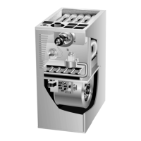
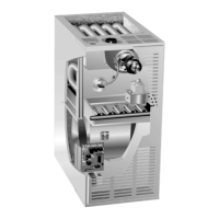
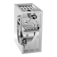
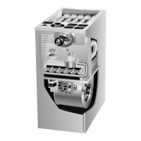
80UHG series units are mid−efficiency gas furnaces used
for upflow or horizontal applications only, manufactured
with tubular heat exchangers formed of aluminized steel.
80UHG units are available in heating capacities of 45,000
to 120,000 Btuh and cooling applications up to 5 tons. Refer
to Engineering Handbook for proper sizing.
Units are factory equipped for use with natural gas. Kits are
available for conversion to LPG operation. 80UHG−1 model
units use electronic (direct spark) ignition. 80UHG−2 and −3
model units are equipped with the Lennox SureLight silicon
nitride ignition system. The 80UHGX unit meets the Califor-
nia Nitrogen Oxides (NO
x
) Standards and California Sea-
sonal Efficiency requirements. All units use a redundant gas
valve to assure safety shut−off as required by A.G.A. or
C.G.A. Units may be installed in upflow or horizontal position.
All specifications in this manual are subject to change. Pro-
cedures outlined in this manual are presented as a recom-
mendation only and do not supersede or replace local or
state codes. In the absence of local or state codes, the
guidelines and procedures outlined in this manual (except
where noted) are recommended only and do not constitute
code.
TABLE OF CONTENTS
Introduction 1. . . . . . . . . . . . . . . . . . . . . . . . . . . . . . . . . . . .
Specifications 2. . . . . . . . . . . . . . . . . . . . . . . . . . . . . . . . . .
Blower Data 3−4. . . . . . . . . . . . . . . . . . . . . . . . . . . . . . . . .
High Altitude 4. . . . . . . . . . . . . . . . . . . . . . . . . . . . . . . . . . .
Parts Identification 5−6. . . . . . . . . . . . . . . . . . . . . . . . . . . .
I Unit Components 6−15. . . . . . . . . . . . . . . . . . . . . . . . . . .
II Installation 15. . . . . . . . . . . . . . . . . . . . . . . . . . . . . . . . . .
III Start Up 15. . . . . . . . . . . . . . . . . . . . . . . . . . . . . . . . . . . .
IV Heating System Service Checks 16−17. . . . . . . . . . .
V Typical Operating Characteristics 18. . . . . . . . . . . . . .
VI Maintenance 19−20. . . . . . . . . . . . . . . . . . . . . . . . . . . .
VII Wiring and Sequence of Operation 21−28. . . . . . . . .
VIII SureLight Troubleshooting Guide 29−34. . . . . . . . . .

Questions and Answers

  • J
    Julie NorrisSep 1, 2025
    What causes Lennox Furnace unit to fail to fire in heating mode when combustion air inducer does not energize?
    • A
      Alyssa WhitakerSep 1, 2025
      If your Lennox furnace unit fails to fire in the heating mode, and the combustion air inducer does not energize, it could be due to: * Miswiring of furnace or improper connections to combustion air inducer. Check for correct wiring and loose connections. Correct wiring and/or replace any loose connections. * Combustion air inducer failure. If there is 120V to combustion air inducer and it does not operate, replace combustion air inducer.
  • T
    Tammy WolfSep 8, 2025
    What to do if Lennox 80UGH fails to fire in heating mode, combustion air blower energizes, and ignitor is energized?
    • S
      Sarah Moss MDSep 8, 2025
      If your Lennox furnace fails to fire in the heating mode, but the combustion air blower and ignitor are energized, you should: * Check that gas is being supplied to the unit. Check line pressure at the gas valve. Pressure should not exceed 13" WC for both natural and propane. Line pressure should read a minimum 4.5" WC for natural and 8.0" WC for propane. * Check for correct wiring and loose connections at the gas valve, multi-pin control amp plugs, or valve. Correct wiring and/or replace any loose connections. * Check that 24V is supplied to the gas valve approximately 35 seconds after heat demand is initiated. Replace the valve if 24V is supplied but valve does not open. Replace the control board if 24V is not supplied to valve.
  • T
    terrence79Nov 12, 2025
    What to do if my Lennox Furnace unit fails to operate in cooling, heating, or continuous fan mode?
    • J
      Joseph ColeNov 12, 2025
      If your Lennox Furnace unit isn't operating in cooling, heating, or continuous fan mode, here's what you can check: * Verify that the main voltage of 120V is supplied to the unit and determine the cause of any power failure. * Inspect the wiring of 120V to the power make up box and transformer, and check the 24V wiring to the control board for correct connections. * Replace any blown fuse, and if it blows again, look for a short circuit. * Ensure the door switch is activated when closed, check wire connections to the switch, replace any loose connectors, and check the switch's continuity in the closed position, replacing it if defective. * Confirm the transformer output is 24V and replace it if defective. * As a last resort, if all other items have been checked, replace the co...
  • A
    annesmithNov 15, 2025
    Why Lennox Furnace burners light but unit shuts down prematurely?
    • D
      Denise WrightNov 15, 2025
      If your Lennox furnace burners light with a heating demand but the unit shuts down prematurely, consider the following: * Check for a restricted exhaust vent and remove any blockage. Also, verify proper vent sizing. * Ensure the sensor is properly located and the sense wire is correctly attached to both the sensor and the control. * Inspect for a broken sensor and test continuity across the sense wire, replacing any damaged components. * Check for resistance between the sensor rod and the unit ground, as well as between the sensor wire and the unit ground, and correct any shorts found in the circuit. * Check the microamp signal from the burner flame. If it's below 0.20 microamps, check the sensor rod for proper location or contamination. Replace, clean, or relocate the flame sen...
  • A
    amywilliamsNov 19, 2025
    What causes Lennox 80UGH to fail to fire in heating mode, and the combustion air blower does not energize?
    • M
      Mrs. Carla ThompsonNov 19, 2025
      If your Lennox furnace fails to fire in heating mode and the combustion air blower doesn't energize, here are some possible causes: * A primary or secondary limit switch may be open. Check continuity across the switch(es). These switches reset automatically upon cool down. Also, check for restrictions on blower inlet and outlet air, and determine the cause for limit activation. * There might be miswiring or improper connections at the limit switch(es). Check for correct wiring and loose connections, correcting the wiring and/or replacing any loose connections. * There could be miswiring or improper connections to the combustion air inducer. Check for correct wiring and loose connections, correcting the wiring and/or replacing any loose connections. * The pressure switch might be s...
  • B
    Brandon JohnsonNov 23, 2025
    How to troubleshoot Lennox 80UGH when it fails to fire, combustion air blower energizes, but ignitor is not energized?
    • D
      Dennis HarringtonNov 24, 2025
      If your Lennox furnace fails to fire in heating mode, the combustion air blower energizes, but the ignitor is not energized, consider these troubleshooting steps: * Ensure that the pressure switch lines are correctly routed. * Remove any obstructions from the pressure lines and/or taps. * Check pressure switch lines for leaks and replace any broken lines. * Check pressure switch lines for condensate. Remove condensate from lines and ensure that the condensate lines are located correctly. * Check the differential pressure across the pressure switch. This pressure should exceed the set point listed on the switch. Also, check for restricted inlet vent and proper vent sizing and run length. * Verify that the proper pressure switch is installed in the unit. Replace pressure switch ...
  • J
    Johnny KeithNov 27, 2025
    What to do if Lennox Furnace control signals low flame sense during heating mode?
    • B
      brent99Nov 27, 2025
      If your Lennox furnace control signals low flame sense during heating mode, consider the following: * Check the sensor rod for proper location on the burner. Properly locate the sensor rod or replace if rod cannot be located correctly. * Check sensor rod for contamination or coated surface. Clean the sensor rod with steel wool or replace sensor. Do not use sand paper to clean rod, as it will contribute to the contamination problem. * Check for correct wiring and loose connections at control or indoor blower motor, correcting the wiring and/or replacing any loose connections. * Check for 120V at the various calls for indoor blower by energizing "Y", "G", and "W" individually on the low voltage terminal strip. Note that when "W’ is energized, the blower is delayed 45 seconds. If the...

Summary

SPECIFICATIONS

BLOWER DATA

FILTER AIR RESISTANCE

HIGH ALTITUDE DERATE

80 UHG PARTS IDENTIFICATION

I-UNIT COMPONENTS

Control Transformer

Provides power to the low voltage section of the unit.

Door Interlock Switch

Shuts down unit when blower door is removed.

Furnace Control (A3) 80 UHG-2, -3 Models

Electronic Ignition

Controls ignition sequence, monitors combustion air pressure switch.

Fan Time Control

Adjusts blower operation time after heat demand is satisfied.

Flame Sensor 80 UHG -2 models

Furnace Control (A3) 80 UHG-1 Model

Ignition Control

Controls ignition sequence, safety circuits, and blower operation.

Safety Circuits

Monitors heating limits and other safety features.

Blower Operation; Fan Off Timings

Manages blower operation and fan off time settings.

Blower Motors and Capacitors

Combustion Air Inducer

Flame Rollout Switches

Primary Limit Control

Secondary Limit Controls

Spark Electrode and Flame Sensor

Gas Valve

Combustion Air Blower Prove Switch

PLACEMENT AND INSTALLATION

Preliminary and Seasonal Checks

Inspect wiring, voltage, and connections before operation.

Heating Start-Up

Procedures for starting the furnace for heating.

Turning Off Gas To Unit

Steps to safely turn off gas supply to the unit.

Safety or Emergency Shutdown

Procedures for immediate shutdown of the unit.

Extended Period Shutdown

Guidelines for shutting down the unit for extended periods.

HEATING SYSTEM SERVICE CHECKS

A.G.A.;C.G.A. Certification

Ensures compliance with gas appliance standards.

Gas Piping

Guidelines for gas supply piping installation and pressure drops.

Testing Gas Piping

Procedures for testing gas lines for leaks and pressure.

Testing Gas Supply Pressure

Verifies gas supply pressure at the unit.

Check Manifold Pressure

Confirms proper regulator adjustment and manifold pressure.

Proper Gas Flow (Approximate)

Flame Signal

TYPICAL OPERATING CHARACTERISTICS

Blower Operation and Adjustment

Describes blower operation and speed settings.

Temperature Rise

Explains how to measure and adjust air temperature rise.

External Static Pressure

Details testing and measurement of external static pressure.

Blower Speed Taps Leadless Motors

Blower Speed Taps Leaded Motors

MAINTENANCE

Filters

Instructions for filter inspection, cleaning, or replacement.

Heat Exchanger and Burners

Procedures for cleaning heat exchanger and burners.

Supply Air Blower

Flue and Chimney

Electrical

Wiring and Sequence of Operation

80 UHG-1 MODEL WITH SURELIGHT CONTROL

Wiring diagram and sequence for the 80UHG-1 model.

80 UHG-1 HEATING SEQUENCE OF OPERATION

NORMAL HEATING MODE

Flowchart for normal heating operation.

ABNORMAL HEATING MODE

Flowchart for abnormal heating operation and troubleshooting.

80 UHG-1 COOLING SEQUENCE OF OPERATION

80 UHG-1 MANUAL CONTINUOUS FAN SEQUENCE OF OPERATION

80 UHG-2 MODEL WITH SURELIGHT CONTROL

HEATING SEQUENCE OF OPERATION

NORMAL HEATING MODE

Flowchart for normal heating operation.

ABNORMAL HEATING MODE

Flowchart for abnormal heating operation and troubleshooting.

HEATING SEQUENCE CONTINUED

NORMAL HEATING MODE

Flowchart for normal heating operation.

ABNORMAL HEATING MODE

Flowchart for abnormal heating operation and troubleshooting.

COOLING SEQUENCE OF OPERATION

NORMAL COOLING MODE

Flowchart for normal cooling operation.

ABNORMAL COOLING MODE

Flowchart for abnormal cooling operation and troubleshooting.

SURELIGHT CONTROL CONTINUOUS HEAT SPEED FAN SEQUENCE OF OPERATION

Troubleshooting-SureLight Control

SURELIGHT - TROUBLE SHOOTING GUIDE

Guide to diagnose and resolve common unit issues.

Lennox 80UGH Specifications

General IconGeneral
BrandLennox
Model80UGH
CategoryFurnace
LanguageEnglish

Related product manuals