Page 42
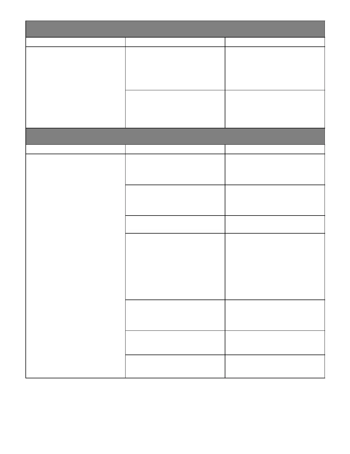
PROBLEM 3: UNIT FAILS TO FIRE IN THE HEATING MODE, COMBUSTION AIR BLOWER DOES
NOT ENERGIZE (CONT.).
Condition Possible Cause Corrective Action/Comments
3.3
− Unit operates with a cooling and con-
tinuous fan demand.
− Combustion air blower will not start
with a Heating demand.
− Diagnostic lights flash the pressure
switch failure code 2 5 minutes after
3.3.1
Miswiring of furnace or improper con-
nections to combustion air blower.
ACTION 1 − Check for correct wiring and loose
connections. Correct wiring and/or replace any
loose connections.
switch failure code 2.5 minutes after
heating demand.
LED#1−Off,
LED#2−Slow Flash
3.3.2
Combustion air blower failure.
ACTION 1 − If there is 120V to combustion air
blower and it does not operate, replace combus-
tion air blower.
PROBLEM 4: UNIT FAILS TO FIRE IN THE HEATING MODE, COMBUSTION AIR BLOWER
ENERGIZES, IGNITOR IS NOT ENERGIZED.
Condition Possible Cause Corrective Action/Comments
4.1
− Unit operates with a cooling and
continuous fan demand.
− Combustion air blower energizes
4.1.1
Pressure switch does not close due
to incorrect routing of the pressure
switch tubing.
ACTION 1 − Check that the pressure switch tub-
ing is correctly routed. Correctly route pressure
switch tubing.
with a heating demand.
− Diagnostic lights flash the pressure
switch failure code 2.5 minutes after
heating demand.
4.1.2
Pressure switch does not close due
to obstructions in the pressure tub-
ing.
ACTION 1 − Remove any obstructions from the
pressure tubing and/or taps.
LED#1−Off
LED#2−Slow Flash
4.1.3
Pressure switch tubing damaged
ACTION 1 − Check pressure switch tubing for
leaks. Replace any broken tubing.
4.1.4
Pressure switch does not close due
to a low differential pressure across
the pressure switch.
ACTION 1 − Check the differential pressure
across the pressure switch. This pressure
should exceed the set point listed on the
switch.
ACTION 2 − Check for restricted inlet and ex-
haust vent. Remove all blockage.
ACTION 3 − Check for proper vent sizing and
run length. See installation instructions.
ACTION 4 − Check voltage to combustion air
blower.
4.1.5
Wrong pressure switch installed in
the unit, or pressure switch is out of
calibration.
ACTION 1 − Check that the proper pressure
switch is installed in the unit. Replace pressure
switch if necessary.
4.1.6
Miswiring of furnace or improper con-
nections at pressure switch.
ACTION 1 − Check for correct wiring and loose
connections. Correct wiring and/or replace any
loose connections.
4.1.7
Pressure switch failure.
ACTION 1 − If all the above modes of failure have
been checked, the pressure switch may have
failed. Replace pressure switch and determine if
unit will operate.

 Loading...


