Page 44
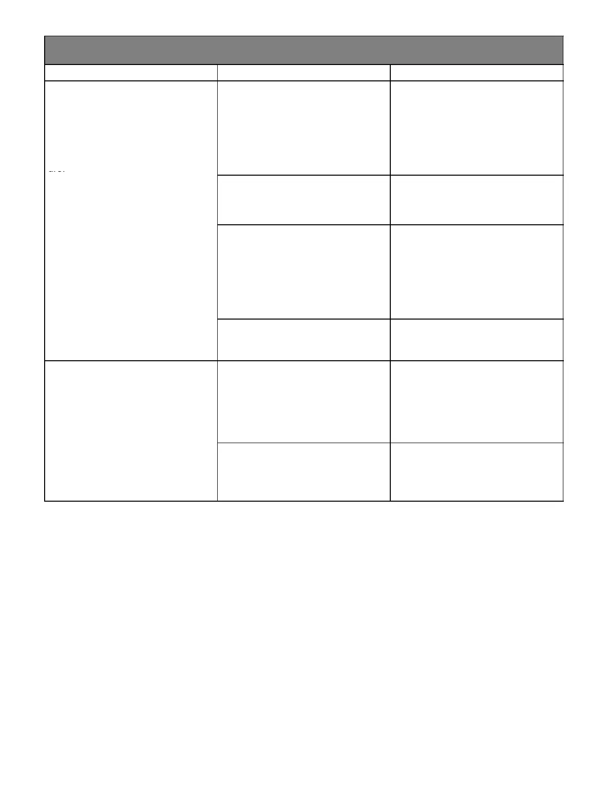
PROBLEM 6: BURNERS LIGHT WITH HEATING DEMAND BUT UNIT SHUTS DOWN
PREMATURELY (CONT.)
Condition Possible Cause Corrective Action/Comments
6.3
− Combustion air blower energizes
with a heating demand.
− Burners light.
− Roll−out switch trips during the
heating demand.
− Diagnostic lights flash roll−out fail-
ure.
6.3.1
Unit is firing above 100% of the
nameplate input.
ACTION 1 − Check that the manifold pressure
matches value listed on nameplate. See installa-
tion instructions for proper procedure.
ACTION 2 − Verify that the installed orifice size
match the size listed on the nameplate or instal-
lation instructions.
ACTION 3 − Check gas valve sensing hose to in-
sure no leaks are present.
ACTION 4 − Check the input rate to verify rate
matches value listed on nameplate.
LED#1−On
LED#2−Slow Flash
6.3.2
Gas orifices leak at the manifold con-
nection.
ACTION 1 − Tighten orifice until leak is sealed.
NOTE: Be careful not to strip orifice threads. AC-
TION 2 − Check for gas leakage at the threaded
orifice connection. Use approved method for
leak detection (see unit instructions).
6.3.3
Insufficient flow through the heat ex-
changer caused by a sooted or re-
stricted heat exchanger.
ACTION 1 − Check for sooting deposits or other
restrictions in the heat exchanger assembly.
Clean assembly as outlined in instruction manu-
al.
ACTION 2 − For 80MGF gas furnaces, check for
proper combustion and flow. CO2 should mea-
sure between 6.0% and 8.0% for natural and
6.5% and 8.5% for L.P. CO should measure be-
low .04% (400PPM) in an air−free sample of flue
gases.
6.3.4
Burners are not properly located in
the burner box.
ACTION 1 − Check that the burners are firing into
the center of the heat exchanger openings. Cor-
rect the location of the burners if necessary.
6.4
− Combustion air blower energizes
with a heating demand.
− Burners light roughly and the unit
fails to stay lit.
− Diagnostic lights flash watchguard
flame failure.
6.4.1
Recirculation of flue gases. This con-
dition causes rough ignitions and op-
eration. Problem is characterized by
nuisance flame failures.
ACTION 1 − Check for proper flow of exhaust
gases away from intake vent. Remove any ob-
stacles in front of the intake and exhaust vent
which would cause recirculation.
ACTION 2 − Check for correct intake and ex-
haust vent installation. See instructions
.
LED#1−Alternating Slow Flash
LED#2−Alternating Slow Flash
6.4.2
Improper burner cross−overs
ACTION 1 − Remove burner and inspect the
cross−overs for burrs, or any restriction or if
crossover is warped. Remove restriction or re-
place burners.

 Loading...


