507581-04 Page 23 of 60Issue 2128
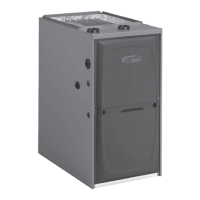
Figure 27.
TYPICAL INTAKE PIPE CONNECTIONS IN UPFLOW DIRECT OR
NON-DIRECT VENT APPLICATIONS
2”
2”
2”
2”
or
AIR
INTAKE
2”
TRANSITION
3”
*2”
Pipe size determined in Table 5
or
* When transitioning up in pipe size, use the shortest length of 2” PVC pipe possible.
NOTE: Exhaust pipe and intake pipe must be the same diameter.
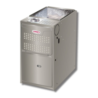
Figure 28.
TYPICAL INTAKE PIPE CONNECTIONS IN HORIZONTAL DIRECT OR NON-DIRECT VENT
APPLICATION (RIGHT-HAND DISCHARGE SHOWN)
2”
2”
2”
2”
or
2”
AIR
INTAKE
TRANSITION
3”
*2”
*2”
* When transitioning up in pipe size, use the shortest length of 2” PVC pipe possible.
NOTE: Exhaust pipe and intake pipe must be the same diameter.
Intake Piping
See Figure 27 through Figure 30
This gas furnace may be installed in either direct vent or non-direct vent applications. In non-direct vent applications, when
intake air will be drawn into the furnace from the surrounding space, the indoor air quality must be considered and guidelines
listed in the Combustion, Dilution & Ventilation Air section must be followed.
Follow the next two steps when installing the unit in Direct Vent applications, where combustion air is taken from outdoors
and ue gases are discharged outdoors. The provided air intake screen must not be used in direct vent applications
(outdoors).
1. Use transition solvent cement or a sheet metal screw to secure the intake pipe to the inlet air connector.
2. Route piping to outside of structure. Continue with installation following instructions given in general guidelines for
piping terminations and in intake and exhaust piping terminations for direct vent sections. Refer to Table 5A through
Table 5C for pipe sizes.
 Loading...