507581-04Page 24 of 60 Issue 2128
Figure 29.
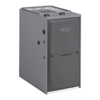
TYPICAL AIR INTAKE PIPE CONNECTIONS
UPFLOW NON-DIRECT VENT APPLICATIONS
Intake
Debris
Screen
(Provided)
NOTE: Debris screen and elbow may be rotated so that the
screen may be positioned to face forward or to either side.
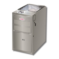
Figure 30.
TYPICAL AIR INTAKE PIPE CONNECTIONS
HORIZONTAL NON-DIRECT VENT APPLICATIONS
Intake
Debris
Screen
(Provided)
OR
PVC Pipe
Coupling
NOTE: Debris screen and elbow may be
rotated so that the screen may be
positioned to face forward or to either side.
(Horizontal Right-Hand Air Discharge Application Shown)
Follow the next two steps when installing the unit in Non–
Direct Vent applications where combustion air is taken
from indoors and ue gases are discharged outdoors.
1. Use eld-provided materials and the factory-provided
air intake screen to route the intake piping as shown in
Figure 29 or Figure 30. Maintain a minimum clearance
of 3” (76 mm) around the air intake opening. The air
intake opening (with the protective screen) should
always be directed forward or to either side in the
upow position, and either straight out or downward in
the horizontal position.
The air intake piping must not terminate too close to
the ooring or a platform. Ensure that the intake air
inlet will not be obstructed by loose insulation or other
items that may clog the debris screen.
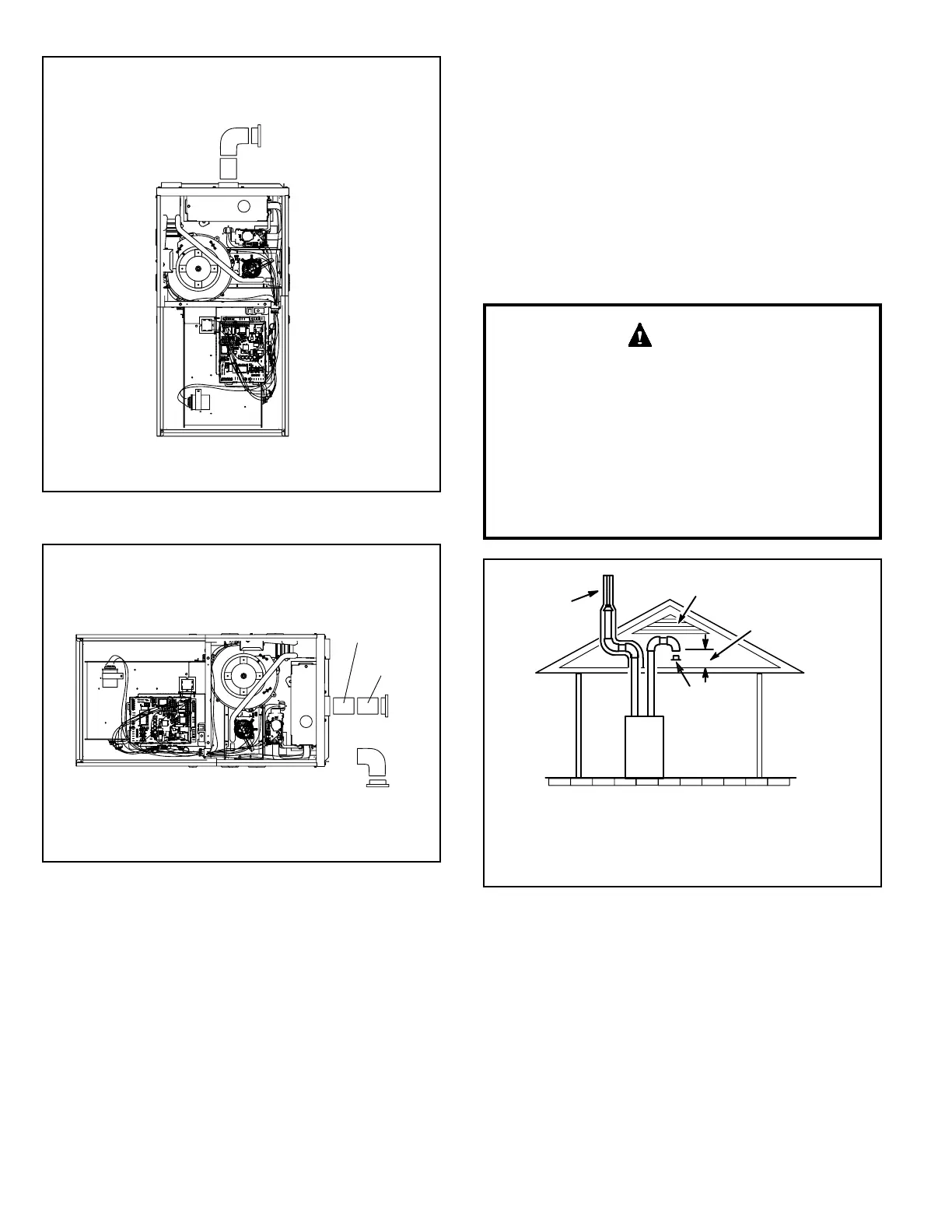
2. If intake air is drawn from a ventilated attic (Figure
31) or ventilated crawlspace (Figure 32) the exhaust
vent length must not exceed those listed in Table 5C.
If 3” diameter pipe is used, reduce to 2” diameter pipe
at the termination point to accommodate the debris
screen.
3. Use a sheet metal screw to secure the intake pipe to
the connector, if desired.
If this unit is being installed in an application with
combustion air coming in from a space serviced by an
exhaust fan, power exhaust fan, or other device which
may create a negative pressure in the space, take care
when sizing the inlet air opening. The inlet air opening
must be sized to accommodate the maximum volume
of exhaust air as well as the maximum volume of
combustion air required for all gas appliances serviced
by this space.
CAUTION
Figure 31. Equipment in Conned Space
(Inlet Air from Ventilated Attic and Outlet Air to
Outside)
NOTE-The inlet and outlet air openings shall each have a free area
of at least one square inch per 4,000 Btu (645mm
2
per 1.17kW) per
hour of the total input rating of all equipment in the enclosure.
Ventilation Louvers
Inlet Air
(Minimum
12 in.(305mm) Above
attic floor)
Roof Terminated
Exhaust Pipe
Furnace
*Intake Debris
Screen
(Provided)
* See Maximum Vent Lengths table
 Loading...