507581-04 Page 55 of 60Issue 2128
6. If ame is not detected after rst ignition trial, the
ignition control will repeat steps 3 and 4 four more
times before locking out the gas valve. The ignition
control will then automatically repeat steps 1 through
6 after 60 minutes. To interrupt the 60 minute period,
move thermostat from “Heat” to “OFF” then back to
“Heat.” Heating sequence then restarts at step 1.
Gas Pressure Adjustment
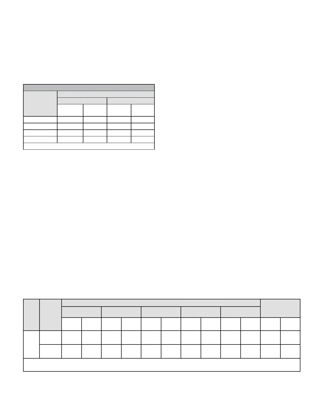
Gas Flow (Approximate)
Table 14.
Gas Meter Clocking Chart
Model
Seconds for One Revolution
Natural LP
1 cu ft
Dial
2 cu ft
Dial
1 cu ft
Dial
2 cu ft
Dial
-30 120 240 300 600
-45 80 160 200 400
-70 55 110 136 272
-110 33 66 82 164
Natural-1000 btu/cu ft LP-2500 btu/cu ft
Furnace should operate at least 5 minutes before checking
gas ow. Determine time in seconds for two revolutions of
gas through the meter. (Two revolutions assures a more
accurate time.) Divide by two and compare to time in Table
14. If manifold pressure matches Table 18 and rate is
incorrect, check gas orices for proper size and restriction.
Remove temporary gas meter if installed.
NOTE: To obtain accurate reading, shut off all other gas
appliances connected to meter.
Supply Pressure Measurement
An inlet pressure post on the inlet side of the gas valve
provides access to the supply pressure. See Figure 67.
Back out the 3/32 Hex screw one turn, connect a piece
of 5/16” tubing and connect to a manometer to measure
supply pressure.
NOTE: Shut unit off and remove manometer as soon as
an accurate reading has been obtained. Take care to re-
tighten the 3/32 Hex screw.
Unit Gas
Manifold Pressure in. w.g. Supply Line
Pressure in.
w.g. 0 - 10000 ft.
0 - 4500 ft. 4501 - 5500 ft. 5501 - 6500 ft. 6501 - 7500 ft. 7501 - 10000 ft.
Low
Fire
High
Fire
Low
Fire
High
Fire
Low
Fire
High
Fire
Low
Fire
High
Fire
Low
Fire
High
Fire
Min Max
All
Sizes
Natural 1.7 3.5 1.6 3.3 1.5 3.2 1.5 3.1 1.7 3.5 4.5 13.0
LP/
Propane
4.5 10.0 4.2 9.4 4.0 9.1 3.9 8.9 4.5 10.0 11.0 13.0
NOTE - A natural to L.P. propane gas changeover kit is necessary to convert this unit. Refer to the changeover kit installation
instruction for the conversion procedure.
Table 18. Manifold and Supply Line Pressure 0 - 10,000 ft.
For proper furnace operation the minimum gas supply
pressure is 4.5” w.c and the maximum gas supply pressure
is 10.5” w.c for natural gas. The minimum gas supply
pressure is 10” w.c. and the maximum gas supply pressure
is 13” w.c. for LP/propane gas.
Manifold Pressure Measurement
1. A manifold pressure post located on the gas valve
provides access to the manifold pressure. See Figure
67. Back out the 3/32 Hex screw one turn, connect a
piece of 5/16” tubing and connect to a manometer to
measure supply pressure.
2. Start unit and allow 5 minutes for unit to reach steady
state.
3. While waiting for the unit to stabilize, observe the
ame. Flame should be stable and should not lift from
burner. Natural gas should burn blue.
4. After allowing unit to stabilize for 5 minutes, record
manifold pressure and compare to value given in
Table 18.
NOTE: Shut unit off and remove manometer as soon as
an accurate reading has been obtained. Take care to re-
tighten the 3/32 Hex screw.
Proper Combustion
Furnace should operate minimum 15 minutes with correct
manifold pressure and gas ow rate before checking
combustion. Take combustion sample beyond the ue
outlet and compare to the tables below. The maximum
carbon monoxide reading should not exceed 100 ppm.
High Altitude Information
NOTE: In Canada, certication for installations at
elevations over 4500 feet (1371 m) is the jurisdiction of
local authorities.
Units may be installed at altitudes up to 10,000 ft. above
sea level. See Table 18 for de-rate manifold values. Units
installed at altitude of 7501 - 10,000 feet require an orice
change. Units installed at altitude of 4501 - 10,000 feet
(1371 to 3048 m) may require a pressure switch change
which can be ordered separately. Table 17 lists conversion
 Loading...