Page 11
NOTE — When the unit is installed in horizontal
applications, a secondary drain pan is recommended.
Refer to local codes.
NOTE — This unit may be installed in left-hand or
right-hand air discharge horizontal applications. Adequate
support must be provided to ensure cabinet integrity.
Ensure that there is adequate room to remove service and
access panels if installing in the horizontal position.
LEFT-HAND DISCHARGE
1. Determine knockouts required for drain line
connections.
2. With access door removed, knock out drain line
opening for installing drain lines.
3. Set unit so that it is sloped toward the drain pan end of
the unit (see figure 24).
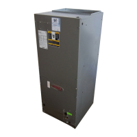
4. The horizontal configuration is shown in figure 17.
Drains
AIR FLOW
KNOCKOUT
LEFT‐HAND DRAINS
Figure 17. Left‐Hand Discharge Configuration
5. If the unit is suspended, the entire length of the cabinet
must be supported. If you use a chain or strap, use a
piece of angle iron or sheet metal attached to the unit
(either above or below) to support the length of the
cabinet. Use securing screws no longer than 1/2 inch
to avoid damaging the coil or filter. See figure 16. Use
sheet metal screws to connect the return and supply air
plenums as required.
RIGHT-HAND AIR DISCHARGE
For horizontal right-hand air discharge, the following field
modifications are required.
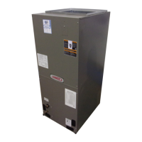
REMOVE BRACKET
SECURING MAIN
DRAIN PAN TO UNIT.
Figure 18. Remove Main Drain Pan Mounting Bracket
(-018 through -036)
1. Remove and set aside blower and coil access covers.
2. Remove bracket(s) securing pan(s) to unit as
illustrated in figures 18 and 19.
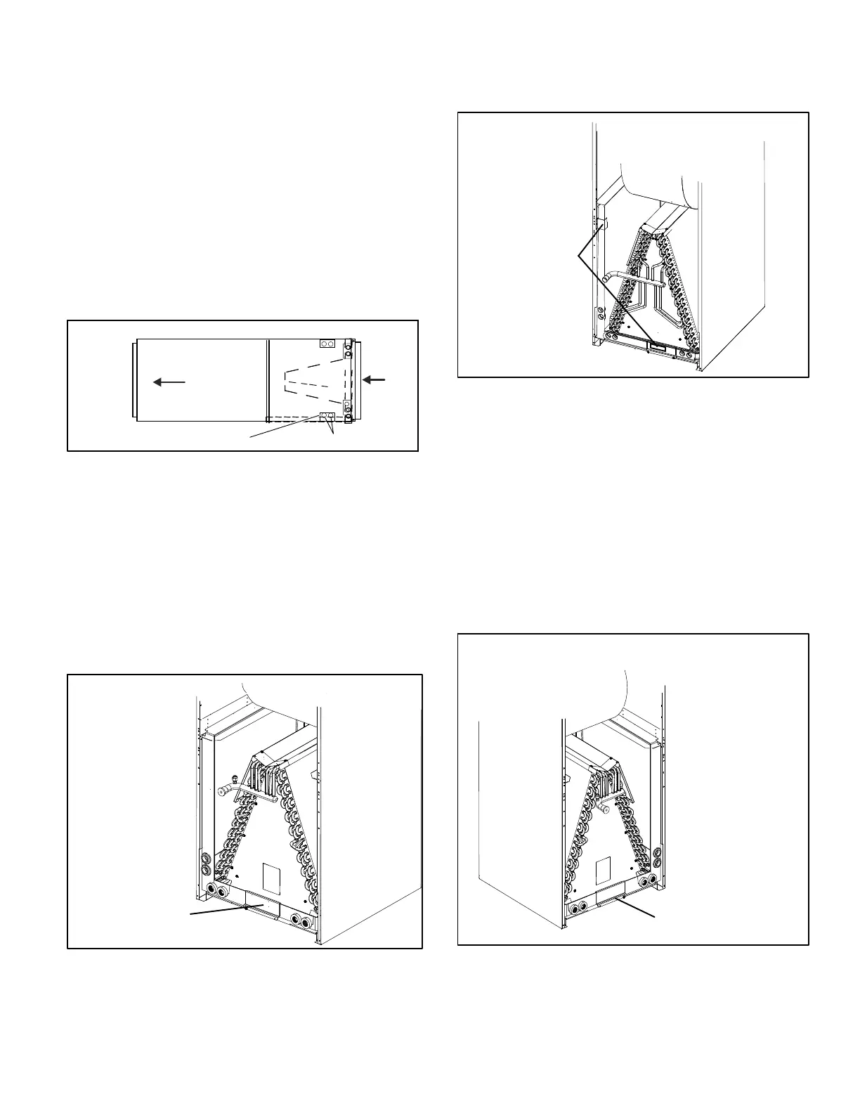
REMOVE BRACKETS
SECURING BOTH
DRAIN PANS TO
UNIT.
Figure 19. Remove Horizontal and Main Drain Pan
Mounting Brackets (-042 through -060)
3. Remove coil assembly, bottom drain pan and
horizontal drain pan as one assembly from the air
handler.
4. Move the horizontal drain pan to the opposite side of
the coil. Be sure drain holes toward the back of the unit
are plugged. Remove the plugs from the front drain pan
ports.
5. Re-install modified coil/drain pan assembly in air
handler in the same orientation as before (figures 20
and 21).
INSTALL BRACKET
SECURING MAIN
DRAIN PAN TO UNIT.
Figure 20. Install Main Drain Pan Mounting Bracket
(-018 through -036)
 Loading...