EasyManua.ls Logo

Lennox CBX25UH Series - User Manual

Lennox CBX25UH Series
22 pages
Print Icon
To Next Page IconTo Next Page
Loading...
Page 1
CBX25UH
Service Literature
Corp. 1241-L9
December 2012
INSTALLATION AND SERVICE PROCEDURE
Revised August, 2018
CBX25UH Series
WARNING
Improper installation, adjustment, alteration, service or
maintenance can cause personal injury, loss of life, or
damage to property.
Installation and service must be performed by a licensed
professional installer (or equivalent) or a service agency.
CAUTION
Physical contact with metal edges and corners while
applying excessive force or rapid motion can result in
personal injury. Be aware of, and use caution when
working near these areas during installation or while
servicing this equipment.
IMPORTANT
The Clean Air Act of 1990 bans the intentional venting of
refrigerant (CFCs, HCFCs and HFCs) as of July 1, 1992.
Approved methods of recovery, recycling or reclaiming
must be followed. Fines and/or incarceration may be
levied for noncompliance.
Table of Contents
Unit Dimensions 2............................
Specifications / Electrical Data 3................
Model Number Information 4...................
Blower Data 4................................
Application 6.................................
Unit Components 6............................
Optional ECB25 Electric Heat 7.................
Configuration Modification 10...................
Electrical Connections 16......................
Wiring Diagrams 17...........................
Start-Up Operations 19........................
Sequence of Operations 20....................
Performance Checklists 21.....................
The CBX25UH are high-efficiency air handler. Several models
are available in sizes ranging from 1‐1/2 through 5-tons. The
CBX25UH is designed for HFC-410A refrigerant.
CBX25UH series units are designed to be matched with either
a13 SEER air conditioner or heat pump, but can be matched
with other air conditioners or heat pumps as noted in the rating
information. See Product Specification bulletin.
This air handler is designed for indoor installation only. As
shipped, the unit is ready for installation in either upflow or
horizontal left-hand. Field modifications are required for
right-hand air discharge applications. Electric heat, down
flow air discharge application kits, air filters and other
various accessories are available and listed in the
CBX25UH Product Specification bulletin for ordering.
All units come with a factory installed check/expansion
valve.
Information contained in this manual is intended for use by
experienced licensed HVAC service technicians only. All
specifications are subject to change. Procedures outlined in
this manual are presented as a recommendation only and do
not supersede or replace local or state codes.
Question and Answer IconNeed help?

Do you have a question about the Lennox CBX25UH Series and is the answer not in the manual?

Summary

Installation and Safety Precautions

Safety Warnings and Cautions

Key safety warnings including danger, caution, and important regulatory notices.

Specifications and Electrical Data

General Data and Connections

Tonnage, line sizes, and coil data for different models.

Blower and Electrical Specs

Motor specs, filter size, voltage, and electrical requirements.

Blower Configuration and Adjustment

Changing Blower Speed

Step-by-step guide to adjust blower speed for optimal airflow.

ESD Safety Precautions

Precautions to protect electronic components from ESD during service.

Blower Performance

Blower Performance Table

CFM data for different models across static pressure ranges.

Unit Components and Application

Electric Heat Installation

Heat Section Installation Procedure

Detailed steps for installing electric heat sections into the air handler.

Heat Installation Safety

Critical safety warnings for electrical shock and physical injury during heat installation.

Electrical Connections

Power Supply Wiring

Connecting field power supply to circuit breakers or terminal blocks.

Configuration and Mounting

Condensate Drainage System

Drain Line Requirements and Traps

Requirements for overflow, secondary drain lines, and traps.

Installation Procedures

Condensate Drain Installation

Steps for installing the condensate drain system.

TXV Relocation and Unit Sealing

Sealing Unit Entry Points

Ensuring an airtight seal around wires, tubing, and lines to prevent moisture issues.

Electrical Connections and Voltage

Electrical Safety Warnings

Critical warnings regarding electric shock and proper wiring practices.

Low Voltage Wiring Diagrams

Heat Pump Wiring Diagrams

Start-Up Procedures

Pre-Start-Up Checks

Comprehensive checklist before energizing the unit for operation.

Sequence of Operation

Operation Checks

Procedures to verify blower, cooling, and heating system functionality.

Performance Checklists (Upflow)

Performance Checklists (Horizontal)

Overview

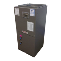
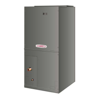
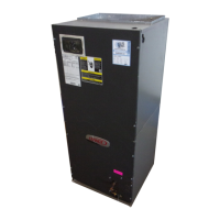
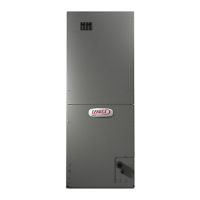
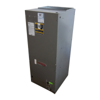
The CBX25UH Series is a line of high-efficiency air handlers designed for indoor installation, compatible with HFC-410A refrigerant. These units are engineered to be matched with 13 SEER air conditioners or heat pumps, though they can be paired with other air conditioning or heat pump systems as specified in the product bulletin. The series offers models ranging from 1-1/2 to 5 tons, catering to various residential and light commercial applications.

Function Description

The primary function of the CBX25UH air handler is to circulate conditioned air throughout a building, working in conjunction with an outdoor air conditioner or heat pump. It houses the indoor coil, blower motor, and control components necessary for air distribution and, when equipped, electric heating.

  • Air Distribution: The unit's blower motor draws return air from the conditioned space, passes it over the indoor coil (for cooling or heating from a heat pump), and then distributes the conditioned air through the supply ductwork. The blower motor is a single-phase direct drive type with a run capacitor and three speed taps (low, medium, high), allowing for flexible airflow adjustments.
  • Cooling Operation: When a cooling demand is initiated by the thermostat, the blower time-delay relay coil is energized, followed by the indoor blower relay. This activates the blower motor and completes the circuit to the outdoor unit's contactor, starting the compressor and outdoor fan motor. For heat pump applications, the reversing valve is also energized to the cooling position. A 1-second motor-on delay is incorporated, and the motor ramps up to 100% CFM. After the cooling demand is met, the motor runs at 100% CFM for 45 seconds before ramping down to stop.
  • Heating Operation (Heat Pump): In heat pump heating mode, the thermostat energizes the blower time-delay relay coil, activating the indoor blower motor and the outdoor unit's compressor and fan. The reversing valve remains de-energized, allowing the heat pump to provide heating.
  • Heating Operation (Electric Heat): If the unit is equipped with optional electric heat, a call for heat from the thermostat energizes a heat sequencer. After a time delay, the heating elements and the indoor blower motor activate. Units with multiple heat sequencers can be configured for multi-stage heating.
  • Emergency Heat (Heat Pump with Electric Heat): When the thermostat is set to emergency heat, the heat pump is locked out, and all heating is provided by the electric heat elements. A jumper on the thermostat subbase ensures the electric heat control transfers to the first-stage heat, allowing the indoor blower to cycle with the electric heat when the fan switch is in AUTO.
  • Refrigerant Management: All units come with a factory-installed check/expansion valve, which is internally installed for a cleaner setup and remains accessible for service. This valve is crucial for regulating refrigerant flow to the indoor coil.

Usage Features

The CBX25UH series offers several features designed for ease of installation, configuration, and reliable operation.

  • Flexible Installation: The unit is designed for indoor installation and, as shipped, is ready for either upflow or horizontal left-hand configurations. Field modifications are required for right-hand air discharge applications. Downflow air discharge application kits are also available as accessories.
  • Blower Speed Adjustment: The cooling blower speed is factory-configured to match the cooling capacity of the air handler's intended outdoor unit. However, if the outdoor unit has a smaller capacity, the blower speed can be easily adjusted by connecting different blower lead wires (RED for low, BLACK for high) to the blower relay harness. The factory-installed plastic cap should be reused on the unused connector.
  • Optional Electric Heat: The air handler supports field-installed electric heat sections, available in various kW ratings. These sections integrate into the control box, providing supplemental or primary heating capabilities.
  • Drain Pan Design: The units include factory-installed fiberglass-filled plastic drain pans. For horizontal applications, a secondary drain pan is recommended, especially when installed over finished living spaces, to prevent water damage from overflow. The drain lines require proper sloping and trapping to ensure complete drainage and prevent air from being drawn through the lines by the blower.
  • Duct System Integration: The air handler is equipped with flanges for connecting supply and return air plenums and ducts. These flanges can also form a filter rack for the air filter, or the filter can be installed within the return air duct system. Proper sizing and insulation of the ductwork are crucial for optimal performance.
  • Transformer: All units utilize a single line voltage to 24VAC transformer, rated at 40VA, located in the control box. 208/240VAC single-phase transformers have two primary voltage taps for compatibility.
  • Circuit Breaker Orientation: For horizontal right-hand discharge installations, the circuit breakers for optional electric heat must be rotated 180 degrees to ensure the "ON" position is correctly oriented upwards, as required by UL 1995.

Maintenance Features

The design of the CBX25UH incorporates considerations for simplified maintenance and service.

  • Access Panels: The air handler features easily removable access panels, secured by screws, to allow technicians to reach internal components such as the blower assembly, coil, and control box.
  • Coil Accessibility: The dual slab coils, arranged in an A-configuration, are designed to easily slide out of the unit cabinet, facilitating cleaning or replacement.
  • TXV Bulb Relocation: The TXV bulb, factory-installed internally, can be relocated to the exterior suction line. This relocation is highly recommended for improved performance and easier access for service.
  • Filter Access: The unit includes a dedicated filter access point, allowing for convenient inspection and replacement of the air filter.
  • Electrical Connections: The control box centralizes line voltage and electric heat connections. Wiring diagrams are provided on the unit access panel and in the manual to guide technicians through electrical troubleshooting and connections.
  • Condensate Drain Testing: After installation, the condensate drain system should be tested by pouring water into the drain pan to ensure complete drainage and check for leaks, which helps prevent future water damage.
  • Sealing the Unit: Maintaining an airtight seal around electrical wires, refrigerant tubing, and condensate lines where they enter the cabinet is important. This prevents warm, moist air from entering the cabinet, which could lead to condensation and blow-off problems, especially in unconditioned spaces. Duct tape or Permagum can be used for sealing.
  • Safety Precautions: The manual emphasizes the importance of disconnecting all power supplies before servicing, replacing all parts and panels before operating, and using copper conductors only. It also warns about electrostatic discharge affecting electronic components and the need to neutralize static charge before performing service. Physical contact with metal edges and corners should be avoided to prevent injury.

Lennox CBX25UH Series Specifications

General IconGeneral
RefrigerantR-410A
StagesSingle Stage
Blower Motor TypeECM
Cabinet MaterialGalvanized Steel
Sound LevelQuiet operation
Operating Voltage208/230V
Unit DimensionsVaries by model
Unit WeightVaries by model
CabinetInsulated
CoilAluminum
Warranty5-Year Limited Warranty on covered components
Cooling Capacity1.5 to 5 Tons
SEER RatingUp to 16 SEER

Related product manuals