Page 9
3. Flip the breaker so that the wires attached to the circuit
breakers terminals are on the left side (see figure 9).
4. Use the black clip to reattach the circuit breaker to the
mounting bracket.
CIRCUIT BREAKERS
AIR HANDLER ACCESS PANEL
CIRCUIT BREAKERS
KNOCKOUTS
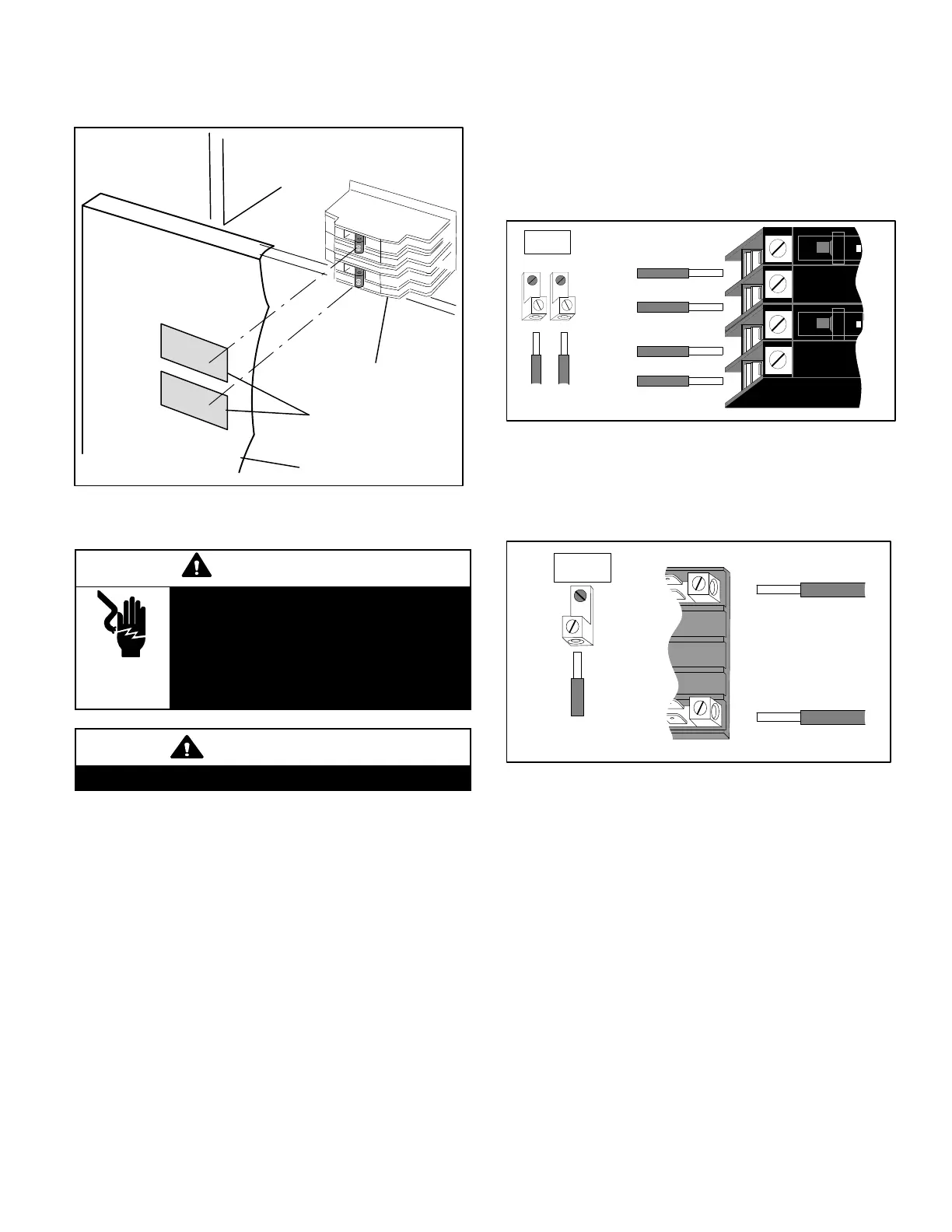
Figure 10. Circuit Breaker Knockouts
BREAKER ELECTRICAL CONNECTIONS
WARNING
Electric shock hazard! - Disconnect all
power supplies before servicing.
Replace all parts and panels before op
erating.
Failure to do so can result in death or elec
trical shock.
WARNING
USE COPPER CONDUCTORS ONLY.
NOTE - Refer to the nameplate on the air handler unit for
minimum circuit ampacity and maximum overcurrent
protection size.
The air handler units are provided with openings to be used
with 1-1/2 inch trade size (1-31/32 inch diameter) conduit.
If you want a single point power supply, refer to the
nameplate on the single point power supply accessory for
minimum circuit ampacity and maximum overcurrent
protection size. Select the proper supply circuit conductors
in accordance with tables 310-16 and 310-17 in the
National Electric Code, ANSI/NFPA No. 70 or tables 1
through 4 in the Canadian Electric Code, Part I, CSA
Standard C22.1.
Refer to figure 31 for typical low voltage field wiring for air
handler/condensing unit and heat pump applications.
Figure 32 is a diagram of the air handler connections and
the heater elements high-voltage wiring.
1. Make wiring connections as follows -
Heaters equipped with circuit breakers—Connect
field power supply wiring to circuit breaker(s). Figure 11
shows L1, L2 and ground GND connections for a
2-breaker configuration.
ON
OFF
60
ON
OFF
60
Figure 11. Field Power Supply Wiring
L1
L2
CIRCUIT 1
L1
L2
CIRCUIT 2
GND
208/240 VOLT FIELD
SUPPLY WIRES
Field Supply
Ground Wires
Heaters equipped with terminal blocks—Connect
field power supply wiring to terminal block(s).Figure 12
shows L1, L2 and ground (GND) connection for a
terminal block configuration.
Figure 12. Terminal Block Connections
L1
L2
GND
208/240 VOLT FIELD
SUPPLY WIRES
FIELD SUPPLY
GROUND WIRES
2. Remove the interface harness from the air handler unit
and connect the 6-pin connector on the heater
assembly to the mating connector on the air handler
unit.
3. For applications using a two‐stage room thermostat
and/or an outdoor thermostat, connect wiring as shown
in figure 31.
CIRCUIT BREAKER COVER INSTALLATION
1. Remove any installed patch plates still present .
2. Remove paper covering adhesive back around
backside perimeter of circuit breaker cover (figure 13).
3. Position the breaker cover over the air handler circuit
breaker opening (figure 14).
 Loading...