Page 14
MOTOR CHECK
Kit #70J11 can be used to check the motor. The kit is
available at the Lennox parts center. If not using the kit,
follow the procedure below. These settings and jumper
placements will bypass the BDC3 control board and
confirm correct motor operation.
Symptom Cause/Procedure
Motor rocks slightly
when starting
This is normal start−up for the variable speed
motor
Motor will not start,
no movement
• Check power at motor
• Check low voltage (24vac R to C) at motor
• Check low voltage connection (G, Y, R, C) at
motor.
• Check for unseated pins on motor harness.
• Test with temporary jumper between R−G.
• Check motor for tight shaft.
• Run moisture check.
Motor rocks, but
won’t start
• Check for loose or compliant motor mount.
• Make sure blower wheel is tight on shaft.
Motor starts, but
varies up and down
or intermittent
• Check line voltage for variation or "sag."
• Check low voltage connections (G, Y, R, C)
at motor
• Check for unseated pins in motor harness.
• Check "DS" on terminal strip for CFM
command
• Check system controls thermostat.
• Perform moisture check.
Motor "Hunts" or
"Puffs" at high CFM
If removing panel or filter reduces "Puffing"
reduce restriction or reduce max airflow.
Stays at low CFM
despite system call
for cool or heat CFM
• Check low voltage thermostat wires and
connections.
• Verify fan is not in delay mode.
• Check "R" missing/not connected to motor.
• Perform motor check.
Stays at high CFM
• Check "R" connection at motor.
• Check fan delay, wait until complete.
• Perform motor check.
Blower will not shut
off
• Current leakage from controls into G, Y or
W?
• Check for Triac switched thermostat or solid
state relay.
Air noise
• Check for proper airflow setting.
• Check/replace filter.
• Use low pressure drop filter.
• Check/correct duct restrictions.
Noisy Blower or
cabinet
• Check for loose blower housing, panels, etc
• If high static causing noise, check for air
whistling through seams in ducts, cabinets or
panels.
• Check cabinet/duct for deformation.
Motor failure has
occurred and
moisture is present
Replace motor and perform moisture check.
*60/65/70% OF COOL SPEED
• Disconnect power to the unit.
• Change delay pin setting on the BDC3 board to #1
• Remove wires from terminal strips in control box.
• Install jumpers between "R" and "Y1" and "R
and "G"
• Turn on power to unit. Blower should operate on
60%, 65% or 70% of cool speed.
• When check is complete disconnect power and
replace delay setting to original position.
*Reduced blower speed for production August 2002 and later
is 70% of COOL speed for ALL model units. Reduced blower
speed for production prior to August 2002 is 65% of COOL for
the −036 units and 60% of COOL for −048 and −060 series
units.
COOL SPEED
• Disconnect power to unit.
• Change delay pin setting on the BDC3 board to #1
• Remove wires from terminal strips in control box.
• Install jumpers between "R" and "Y1", "R" and
"Y2","R" and "DS"and "R" and "G".
• Turn on power to unit. Blower should operate on
cool speed.
• When check is complete disconnect power and
replace delay setting to original position.
HEAT SPEED
• Disconnect power to the unit.
• Change delay pin setting on the BDC3 board to #1
• Remove wires from terminal strips in control box.
• Install jumper between "R" and "W1".
• Turn on power to unit. Blower should operate on
heat speed.
• When check is complete disconnect power and
replace delay setting to original position.
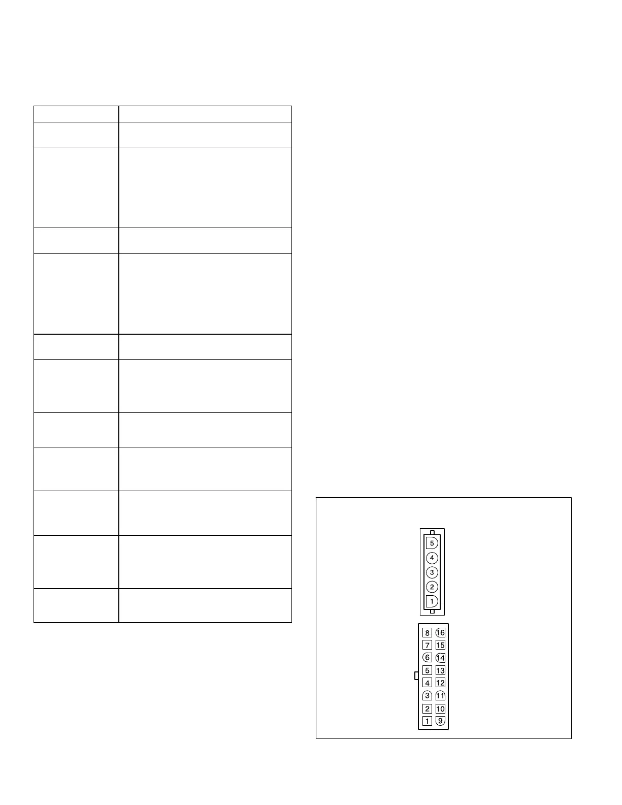
Notes on 5 Pin AC Line Connection
(See Figure 6)
• The motor connects directly to the line.
• Pins 1 & 2 are jumpered in the harness for 115V
operation.
• Make sure power is off before inserting power
connector.
• Plug is polarized.
Notes on 16 Pin Control Connection
(See Figure 6)
• Control functions (G, Y1, Y2) may be active at greater
than .5 x control transformer voltage.
• Do not apply 24vac to either "Out" pin (8 or16).
• High voltage on control pins will destroy motor.
• Make sure pins are fully seated in connector and
housing.
• Verify common connection from transformer (C or B)
to C1, C2 (Pin 1 and Pin 3).
• Once common is verified, test motor by applying
24vac (R) to control pins.
AC Line
AC Line
Gnd
Line 1 and 2 will be
connected for 120 Vac
applications only
Out −
Adjust
Y1
Delay
Common 2
W/W1
Common 1
Out+
G (fan)
Y/Y2
EM ht/W2
24Vac (R)
Heat
DS/Pwn (Speed)
O (Rev Valve)
Cool
FIGURE 6
Motor Connectors
(Cable Half)
5 Pin Power
connector
16 Pin Control
Connector

 Loading...


