Page 33
VIII−TYPICAL OPERATING CHARACTERISTICS
A−Blower Operation and Adjustment
NOTE− The following is a generalized procedure and
does not apply to all thermostat controls.
1− Blower operation is dependent on thermostat
control system.
2− Generally, blower operation is set at thermostat
subbase fan switch. With fan switch in ON position,
blower operates continuously. With fan switch in AUTO
position, blower cycles with demand.
3− In all cases, blower and entire unit will be off when the
system switch is in OFF position.
B−External Static Pressure
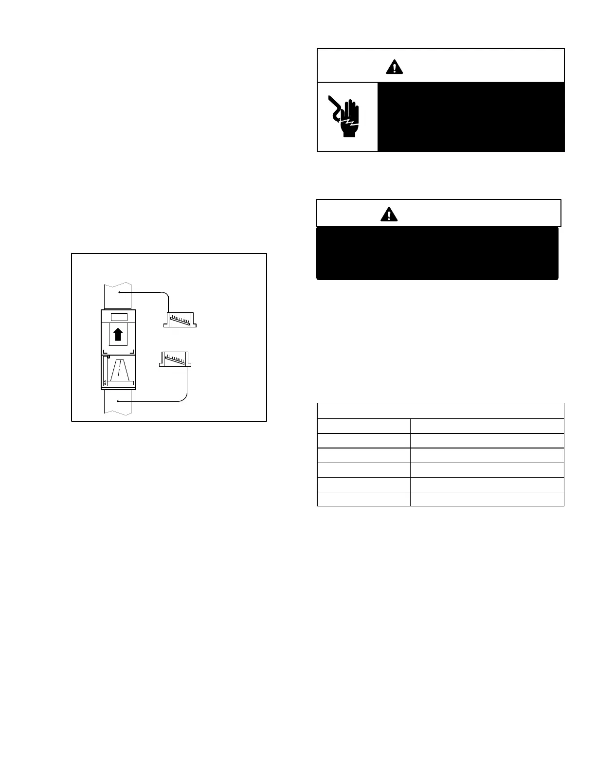
1. Measure tap locations as shown in figure 32.
FIGURE 32
STATIC PRESSURE TEST
MANOMETER
SUPPLY
RETURN
UNIT SHOWN IN
UPFLOW POSITION
+
_
2. Punch a 1/4" (6mm) diameter hole in supply and return
air plenums. Insert manometer hose flush with inside
edge of hole or insulation in the supply plenum only. Seal
around the hose with permagum. Connect the other end
of the hose to the zero end of the manometer. Leave the
other end of the manometer open to the atmosphere.
3. With only the blower motor running and the
evaporator coil dry, observe and take note of the
manometer reading.
4. Repeat step 2 for the return air plenum. Insert
manometer hose to the opposite end of the zero side
of the manometer. Leave the zero side of the
manometer open to atmosphere.
5. Repeat step 3.
6− Add the absolute values of the supply air reading and the
return air reading to get the external static pressure of the
unit. For example −.20 in.wg. on the return and +.30 in.wg.
on the supply result in external static pressure of .50 in.wg.
External static should not exceed .80" w.g. (200Pa)
Adjust blower motor speed to deliver the air desired
according to job requirements.
7− Seal around the holes when the check is complete.
IX−MAINTENANCE
WARNING
Electric shock hazard. Can cause injury
or death. Before attempting to perform
any service or maintenance, turn the
electrical power to unit OFF at discon-
nect switch(es). Unit may have multiple
power supplies.
At the beginning of each heating/cooling season, the
system should be checked as follows:
A−Filters
IMPORTANT
Filter access panel must be in place during unit
operation. Excessive warm air entering the unit
may result in water blow−off problems.
To remove filter, loosen the thumb screws holding the
filter panel in place. Slide filter out of the guides on either
side of cabinet, insert new filter and replace panel. Some
models come with a spacer so standard size filters can
be used. Filters should be inspected monthly and must
be replaced when dirty to ensure proper blower coil
operation. See table 15 for replacement filter sizes or
see the sticker located on the filter access door
specifying the size of the standard throw-away filter
which is used with the unit.
TABLE 15
CBX32MV FILTER SIZES
Unit Filter Size
CBX32MV018/024 15" X 20" (381mm X 508mm)
CBX32MV−024/030 20" X 20" (508mm X 508mm)
CBX32MV−036 20" X 22" (508mm X 599mm)
CBX32MV−048, −060 20" X 24" (508mm X 610mm)
CBX32MV−068 20" X 25" (508mm X 635mm)
B−Supply Air Blower
1- Check and clean blower wheel.
2- Motors are pre−lubricated for extended life; no further
lubrication is required.
C−Electrical
1- Check all wiring for loose connections.
2- Check circuit breaker located in unit control box.
3- Check for correct voltage at unit (unit operating).
4- Check amp-draw using a True root mean square
(RMS) amperage meter. Typical clamp−on ammeters
do not read current accurately.
5- Check to see that heat (if applicable) is operating.
D−Insulation
Outdoor piping insulation should be inspected yearly for
deterioration. If necessary, replace with same materials.

 Loading...


