Page 19
CBX32MV SERIES
SENSOR CONNECTIONS AND WIRING
REQUIREMENTS
The following are sensor connections and wiring
requirements for the discharge air and outdoor air sensors.
Discharge Sensor (DAT)
The Air Handler Control has two screw terminals marked
Discharge Air Sensor. The sensor is REQUIRED for
EVENHEAT operation and is field mounted and ordered
separately using Lennox Catalog # 88K38.
In the EVENHEAT mode, the discharge air sensor cycles
the electric heating elements as needed to maintain the Air
Handler control EVENHEAT jumper selected discharge
setpoint.
The discharge air sensor should be mounted downstream
of the electric heat elements as illustrated in figure 15,
detail A. It must be placed in a location with unobstructed
airflow, where other accessories (such as humidifiers, UV
lights, etc.) will not interfere with its accuracy.
Wiring distance between the Control and the discharge air
sensor should not exceed 10 feet (3 meters) when wired
with 18−gauge thermostat wire.
Outdoor Air Sensor
This is a two screw terminal for connection to a Lennox
X2658 outdoor temperature sensor. The Control takes no
action on the sensor status other than to communicate the
temperature to the RSBus network. Wiring distance
between the AHC and outdoor temperature sensor should
not exceed 200 feet when wired with 18−gauge thermostat
wire.
S Minimum temperature: −40ºF (−40ºC)
S Maximum temperature: 70ºF (158ºC)
AIR HANDLER CONTROL 9−PIN CONNECTOR (P8)
1. Air Handler (no electric heat) Two wire factory
harness (wired to pins 7 and 8) which provides 230
VAC power to Air Handler Control.
2. Air Handler (with electric heat) Eight wire factory
harness (all pin position are wired as noted in table 5).
NOTE See figure 15, detail B for wire colors.
Table 5. Electric Heat Connection (P8)
Position Function / Description
1 Heat stage 1 relay coil
2 Heat stage 2 relay coil
3 Relay coil return
4 Heat stage 3 relay coil
5 Heat stage 4 relay coil
6 Heat stage 5 relay coil
7 L1 230VAC supply from heater kit
8 L2 230 VAC supply from heater kit
9 Not Used
CONTROL CONNECTIONS AND WIRING
REQUIREMENTS
This sections provides information on communicating and
non−communicating control connections and wire run
lengths.
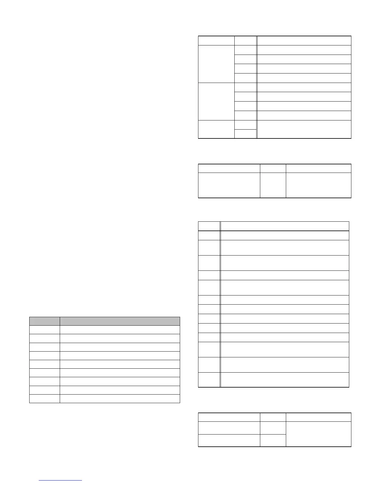
Table 6. Air Handler Control Connections
Communicating
Label Label Function
Thermostat
R 24VAC
i+ RSbus data high connection
i− RSbus data low connection
C 24VAC command (ground)
Outdoor Unit
R 24VAC
i+ RSbus data high connection
i− RSbus data low connection
C 24VAC command (ground)
Link
i+
Not used.
i−
Table 7. Run Length Communicating
Wire Run Length AWG # Insulation/Core Types
Maximum length of wiring
for all connections on the
RSbus is limited to 1500
feet (457 meters).
18
Color−coded, temperature
rating 95
º
F (35
º
C) minimum,
solid core. (Class II Rated
Wiring)
Table 8. Air Handler Control Connections
Non−Communicating
Label Function
W1 First−stage heating demand.
W2
Second stage heating demand. W1 input must be active to
recognize second stage heat demand. .
W3
Third stage heating demand. W1 and W2 inputs must be
active to recognize third stage heat demand.
G 24VAC signal indicates the presence of a demand.
Y1 and
Y2
First and second stage cooling inputs.
C 24VAC common.
R 24VAC power.
DH Use in communicating system only
H 24VAC output for humidification.
L Use in communicating system only
O
Reversing Valve input. (Energized by thermostat in cooling
mode.)
DS
Blower speed control input for Harmony Zoning or thermo-
stat de−humidification control.
DS
Blower speed control input for Harmony Zoning or thermo-
stat de−humidification control.
Table 9. Run Length Non−Communicating
Wire Run Length AWG # Insulation/Core Types
Less than 100’ (30m) 18
Color−coded, temperature
rating 95
º
F (35
º
C) minimum,
solid core. (Class II Rated
Wiring)
More than 100’ (30m) 16

 Loading...


