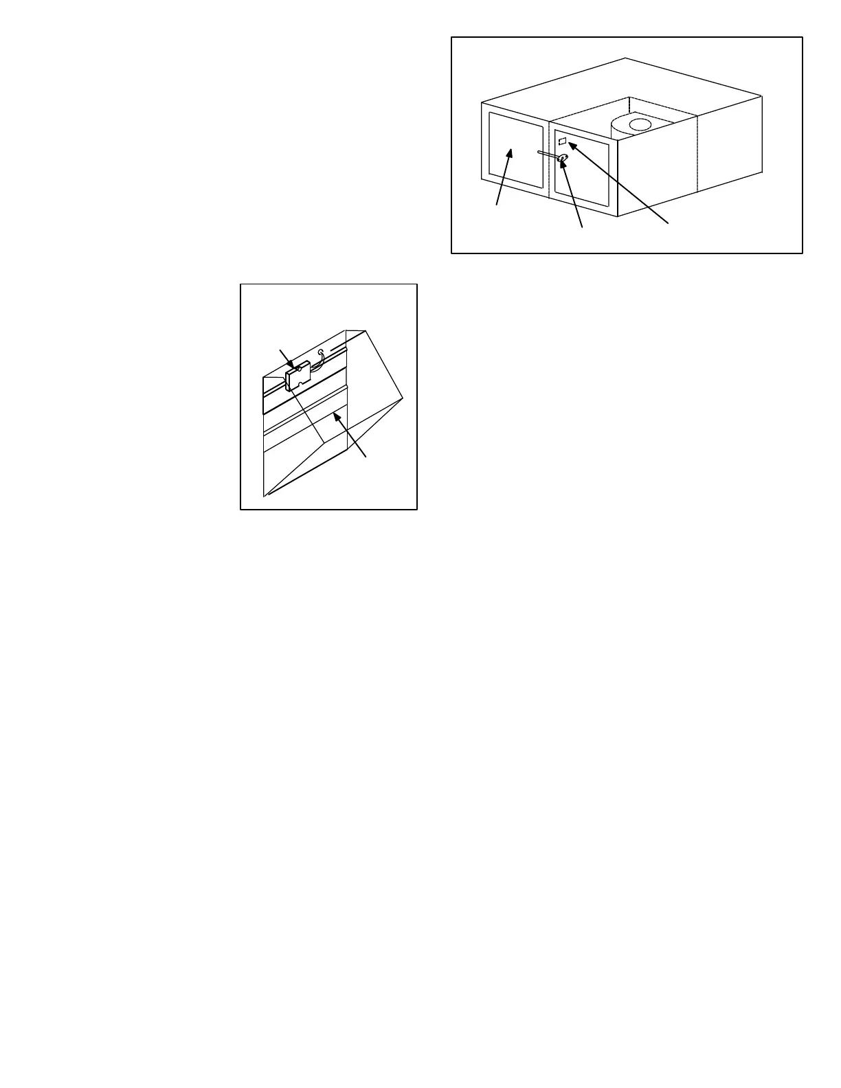
FIGURE 25
ENTHALPY SENSOR
ALL ECONOMIZERS
ENTHALPY
SENSOR
OUTDOOR
AIR DAMPERS
Page 50
8-Minimum Positioner
The second type of adjustment which may be made at
the control is the minimum position of the outdoor
damper blades. Each economizer has a minimum poĆ
sitioner switch (potentiometer) which allows the outĆ
door dampers to be adjusted to a preset minimum
position. This allows a preset amount of air exchange
at all times during unit operation. When unit operation
stops, the dampers drive fully closed. The potentiomĆ
eter is located on the enthalpy control face (modulatĆ
ing economizer) or on the damper motor (three posiĆ
tion economizer).
9-Enthalpy Sensor
The enthalpy sensor
is located on the outĆ
side portion of the outĆ
door damper blades
(as shown in figure
25). The sensor moniĆ
tors the total heat conĆ
tent of the outdoor air
(temperature plus huĆ
midity) and sends the
information to the enĆ
thalpy control. The
enthalpy control uses
the information to deĆ
termine if outdoor air can be used for cooling.
10-Mixed Air Sensor
The sensor measures the resultant temperature of
the mixed air downstream of the evaporator coil. The
mixed air temperature is used by the enthalpy control
when outdoor dampers are open to help determine
whether outdoor air dampers should close. ModulatĆ
ing economizers are equipped with a single mixed air
sensor. Three position economizers are equipped
with a separate sensor (switch) and sensing bulb
which are connected by a cap tube.
The mixed air sensor (bulb) is located in the supply air
stream. The sensor (modulating economizer) or
sensing bulb (three position economizer) fits through
a factory supplied hole in the panel dividing the unit reĆ
turn and supply air (see figure 26). The three position
economizer sensor (switch) mounts to pre-drilled
holes in the unit panel dividing return and supply air.
11-Night Relay
Optional night relay must be added to economizer
when night setback functions are desired with electroĆ
mechanical control systems. Kit includes a DPDT
relay which is hard-wired to the economizer harness.
MIXED AIR SENSOR
CHP16 UNIT
SENSOR HOLE
LOCATION
CONTROL
HARNESS
SUPPLY
AIR
FIGURE 26
12-Warm Up Kit
An optional warm up kit may be added to either
REMD16 or EMDH16 economizer (except CHA/
CHP16/20 units using a Honeywell W7400 or T7300
Control System). The Warm Up Kit holds the dampers
closed during night setback and morning warm up.
When the first thermostat demand of the day is satisĆ
fied, the warm up kit opens the outdoor dampers to
minimum position. The warm up kit mounts to the
CHA/CHP16/20 in the control mounting area of the
blower compartment. The kit plugs into the unit wiring
harness inline between the unit and the economizer.
13-Condenser Coil Guard Kit
Optional condenser coil guard kit is available for all units. The
kit includes PVC coated steel wire coil guard which is field
installed. OPTIONAL ACCESSORIES (see table of conĆ
tents) show guard quantity per unit.
14-DF16 Downflow Filter Kit
Optional downflow filter kit may be added to any CHP16 unit
not equipped with factory installed filter brackets. The kit
provides a means for filtering (downflow) return air inside
the cabinet. The kit includes rails which install in the blower
compartment and allow the (one inch thick) filter (furnished)
to slide in. Two kits are available. DF16-41 installs in -024,
-030, and -036 units and DF16-65 installs in -042, -048 and
-060 units.
15-Timed-Off Control Kit
Optional field installed timed-off controls prevent the CHA/
CHP16/20 compressors from short cycling. After a thermoĆ
stat demand, automatic reset timed-off control keeps comĆ
pressor off for 3-7 minutes.
NOTE - Some electronic thermostats have built in time
delay. Field installed time delay is not needed on these
applications.
16-OptionalĂCompressorĂMonitorā
Optional compressor monitor can be installed in all units to
provide low ambient protection for the compressor. The
monitor is a N.O. temperature switch located in the control
box area. It is wired in series with the compressor contactor.
When ambient temperature drops below 40°F, the switch
opens and de-energizes the compressor contactor thereby
protecting the compressor from low ambient operation.
 Loading...