23
156.2
A
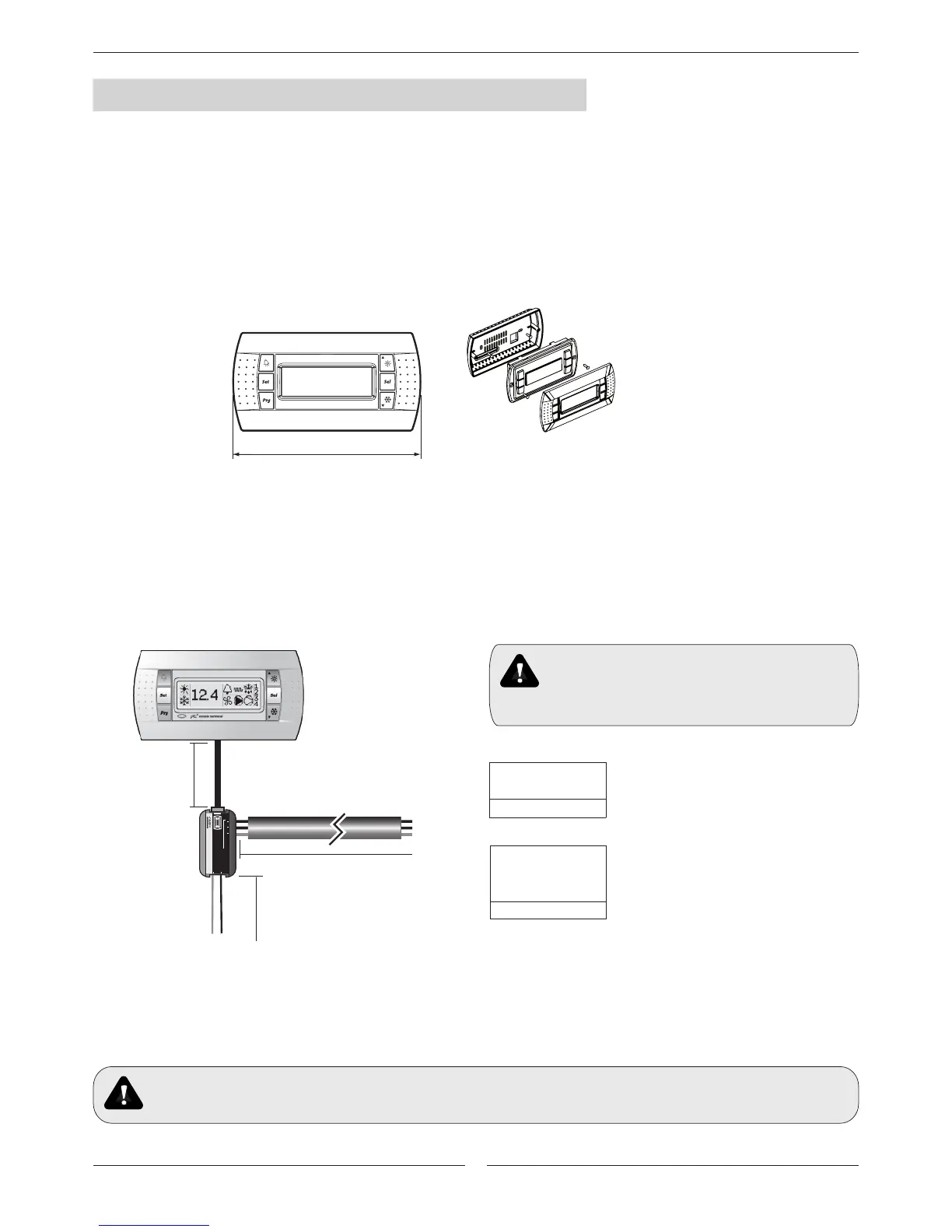
RJ12 – Power supply
RS485 24 Va
c
G
G0
– +
GND
DC41
Max. L=10m.
92
91
90
93 94
DT41
ASSEMBLY AND INSTALLATION INSTRUCTIONS
Installation instructions:
1. Pass the telephone cable through the hole in the rear of the casing.
2. Fasten the rear of the casing to the box using the round-head screws.
3. Connect the telephone cable to the RJ12 terminal of the DC41.
4. Rest the front panel on the rear of the casing and fasten the assembly using the countersunk screws, as shown in Fig. 8.3.
5. Finally, click the frame in place.
DC41.
Electrical connections:
1. Disconnect the power supply before working on the DC41 during operations of assembly, maintenance and replacement.
2. Make the connection between the “DT41” power supply and the DC41 terminal using the telephone cable (80 cm)
supplied. If the cable is not long enough, use a pin-to-pin telephone cable with a maximum length of 10 m.
Fig. 8.3
Fig. 8.4
Thelefone cable
Max. L.=200m. AWG20.
Keep the DC41’s inductive load cables separate from
those of any power devices (contactors, etc.) in order to
prevent electromagnetic interference.
Do not lay power and communications cables together
- Connect from the electrical box in the outdoor unit to DT41 device:
. 91 and 92 terminal blocks respectively to Tx+ and Tx -. (Twisted pair for communications).
. 93 and 94 terminal blocks respectively to GO and G. (Twisted pair for power 24VAC).
. 90 to GND. (shield).
Max. L.=200m
Ø=1,5mm
2
2 x TWISTED PAIR
SCREEN WIRE AWG20
Max. L.=100m
1 x TWISTED PAIR
SCREEN WIRE AWG20
+ 2 x 1,5 mm
2
Max. L.=200m
Insert 120Ω terminal resistor between + y - of DT40 device (see electrical drawing) for lines longer then 20m.

 Loading...
