EasyManua.ls Logo

Lennox ECB38-20CB - User Manual

Lennox ECB38-20CB
12 pages
Print Icon
To Next Page IconTo Next Page
Loading...
©2017 Lennox Industries Inc.
Dallas, Texas, USA
Page 1
THIS MANUAL MUST BE LEFT WITH THE
HOMEOWNER FOR FUTURE REFERENCE
WARNING
Electric Shock Hazard.
Can cause injury or death.
Foil-faced insulation has conductive
characteristics similar to metal. Be sure there
are no electrical connections within 1/2ʺ
of the insulation. If the foil-faced insulation
comes in contact with electrical voltage, the
foil could provide a path for current to pass
through to the outer metal cabinet. While
the current produced may not be enough to
trip existing electrical safety devices (e.g.,
fuses or circuit breakers), the current can be
enough to cause an electrical shock hazard
that could cause personal injury or death.
WARNING
Improper installation, adjustment, alteration, service
or maintenance can cause property damage, personal
injury or loss of life. Installation and service must be
performed by a licensed professional HVAC installer or
equivalent, service agency, or the gas supplier.
INSTALLATION
INSTRUCTIONS
ELECTRIC HEAT SECTIONS
507805-01
12/2017
ECB38 Series Units
Shipping and Packing List
Package 1 of 1 contains:
1 – Assembled electric heat section
1 – Bag assembly containing the following:
Screws - 6 each
Wiring diagram - 1 each
Circuit breaker cover - 1 each
2 – Adhesive-backed foam seals
Check equipment for shipping damage; if found, immedi-
ately contact the last carrier.
WARNING
Electric shock hazard! - Disconnect all power
supplies before servicing.
Replace all parts and panels before
operating.
Failure to do so can result in death or
electrical shock.
ELECTRIC HEAT WILL NOT OPERATE
IF IT IS NOT CONFIGURED (SET UP)
THROUGH THE AIR HANDLER
CONTROL (AHC).
SEE CONFIGURATION PROCEDURE,
FIGURE 12 ON PAGE 9.
IMPORTANT INFORMATION FOR INSTALLER
H
H
CONFIGURE ELECTRIC HEAT
ECB38
®
OR iComfort
®
S30 INSTALLER
SETUP, ELECTRIC HEAT MUST BE MANUALLY CONFIGURED.
Question and Answer IconNeed help?

Do you have a question about the Lennox ECB38-20CB and is the answer not in the manual?

Summary

INSTALLATION INSTRUCTIONS

Shipping and Packing List

Lists components included in the package for the electric heat section.

Installer Information and Safety Warnings

Key installer guidance, electric shock, and improper installation warnings.

Electric Heat Sections

General Information

Provides general guidance, local codes, and safety requirements for installation.

Heat Section Installation Procedures

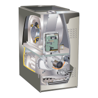
Step-by-step instructions for physically installing the heat section into the air handler.

Circuit Breaker Installation

Circuit Breaker and Patch Plate Configuration

Details configuration of circuit breakers and patch plates for different unit models.

Circuit Breaker Cover and Sensor Setup

Circuit Breaker Cover Installation

Instructions for installing the circuit breaker cover to ensure an airtight seal.

Discharge Air Temperature Sensor

Explains the purpose and function of the discharge air sensor for EVENHEAT operation.

Electrical Connections and Unit Start-Up

Air Handler Control 9-Pin Connector Wiring

Describes wiring connections between the air handler and heat section via a 9-pin connector.

Unit Start-Up Procedures

Steps for starting up the unit, including blower speed selection.

Unit Configuration

Air Handler Control Checkout

Procedure to check the air handler control's unit size code and heat section detection.

Unit Size Code Configuration

Heat Mode Selection and Configuration

Heat Mode Selection

Guide to selecting between Standard and EVENHEAT modes for electric heat.

Configuring;Detecting Electric Heat Sections

Steps to configure the AHC to detect installed electric heat sections.

EVENHEAT Operation Details

Wiring Diagram Cross-Reference

Overview

The provided manual describes the Lennox ECB38 Series Electric Heat Sections, designed for field-installation with CBA38MV series air handler units. These electric heat sections provide supplemental heating and are available in single-phase and three-phase voltages. Single-phase ECB38 heat sections are equipped with either terminal blocks or circuit breakers.

Function Description:

The ECB38 Series Electric Heat Sections are designed to provide electric heating for residential and commercial HVAC systems when paired with a Lennox CBA38MV air handler unit. They integrate with the air handler control (AHC) to deliver heat, supporting both Standard Heat and EVENHEAT modes. In EVENHEAT mode, the AHC uses a discharge air temperature sensor to modulate the electric heating elements to maintain a specified temperature range. The system can activate multiple stages of electric heat based on demand from the room thermostat.

Important Technical Specifications:

  • Compatibility: Designed for use with Lennox CBA38MV series air handler units.
  • Voltage: Available in single-phase and three-phase configurations.
  • Components: Includes an assembled electric heat section, screws (6 each), a wiring diagram, a circuit breaker cover, and adhesive-backed foam seals.
  • Electrical Connections: Requires proper supply circuit conductors in accordance with National Electric Code (ANSI/NFPA No. 70) or Canadian Electric Code, Part I, CSA Standard C22.1.
  • Air Handler Control (AHC): The AHC (Lennox Catalog # 16B27 for CBA38MV) manages the electric heat sections. It features a 9-pin connector for communication with the heat section.
  • Discharge Air Sensor (DAT): Required for EVENHEAT operation (Lennox Catalog # 88K38), field-mounted, and connects to two screw terminals on the AHC. The sensor measures discharge air temperature to control heating elements.
  • Blower Speed Taps: The AHC allows selection of blower speeds for different operating modes (AC, HP, AC with Electric Heat, HP with Electric Heat) using specific pin configurations (e.g., COOL PIN #2, HEAT PIN #4 minus).
  • Relay Coils: The electric heat sections use 22V DC pilot relays for activating heating stages.
  • Circuit Breakers: Single-phase ECB38 heat sections are equipped with either terminal blocks or circuit breakers. Circuit breakers may need to be rotated 180° for downflow applications.
  • Foil-faced Insulation Warning: Emphasizes that foil-faced insulation has conductive characteristics and must not come into contact with electrical voltage, as it can create a shock hazard. Maintain at least 1/2" clearance from electrical connections.

Usage Features:

  • Configuration: Electric heat must be configured (set up) through the air handler control (AHC) for proper operation. This involves selecting the unit size code and heat mode (Standard or EVENHEAT).
  • EVENHEAT Mode: This advanced mode uses the discharge air temperature sensor to precisely control electric heating elements, maintaining a consistent discharge air temperature. The control turns ON or OFF elements based on demand to achieve specified temperature ranges (e.g., 85°F, 100°F, 115°F/130°F).
  • Staging: The system supports multiple stages of electric heat, activating them sequentially based on thermostat demand (W1, W2, W3 inputs).
  • Blower Operation: The indoor blower motor starts immediately upon activation of the first electric heat pilot relay, delivering CFM as set by the heating mode jumper.
  • Thermostat Integration: The system integrates with room thermostats for heat demand signals.
  • Installer Setup: Electric heat must be manually configured prior to running iComfort WiFi® or iComfort® S30 Installer Setup.

Maintenance Features:

  • Installation and Service: Emphasizes that installation, adjustment, alteration, service, or maintenance must be performed by a licensed professional HVAC installer or equivalent, service agency, or the gas supplier to prevent property damage, personal injury, or loss of life.
  • Power Disconnection: All power supplies must be disconnected before servicing the unit to prevent electric shock.
  • Part Replacement: All parts and panels must be replaced before operating the unit.
  • Circuit Breaker Cover: If the air handler is installed in an unconditioned space, the provided circuit breaker cover must be installed and properly sealed with silicone to prevent warm, moist air from entering the control panel and causing condensation.
  • Wiring Diagram: A wiring diagram sticker should be affixed to the blower scroll, aligned with the CB unit wiring diagram sticker, for future reference.
  • Safety Precautions: Advises caution when handling sheet metal edges and recommends wearing gloves and protective clothing during installation and service.
  • Code Compliance: Installation must conform with federal, state, and local codes, including NFPA No. 90A and 90B standards.

Lennox ECB38-20CB Specifications

General IconGeneral
BrandLennox
ModelECB38-20CB
CategoryHeat Pump
LanguageEnglish

Related product manuals