EasyManua.ls Logo

Lennox Elite EL22XPV-048 User Manual

Lennox Elite EL22XPV-048
22 pages
To Next Page IconTo Next Page
Page #1 background imageLoading...
Page #1 background image
©2023 Lennox Industries Inc.
Dallas, Texas, USA
Page 1
WARNING
Improper installation, adjustment, alteration, service
or maintenance can cause property damage, personal
injury or loss of life. Installation and service must be
performed by a licensed professional HVAC installer or
equivalent, or service agency.
WARNING
To prevent serious injury or death:
1. Lock-out/tag-out before performing maintenance.
2. If system power is required (e.g., smoke detector
maintenance), disable power to blower, remove fan
belt where applicable, and ensure all controllers
and thermostats are set to the “OFF” position before
performing maintenance.
3. Always keep hands, hair, clothing, jewelry, tools, etc.
away from moving parts.
CAUTION
As with any mechanical equipment, contact with sharp
sheet metal edges can result in personal injury. Take
care while handling this equipment and wear gloves and
protective clothing.
INSTALLATION
INSTRUCTIONS
HEAT PUMP
508302-01
9/2023
Elite
®
Series EL22XPV Units
PACKING LIST
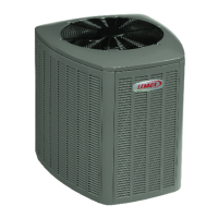
OUTDOOR UNIT
WARRANTY
CERTIFICAT E
RAST 6-PIN
CONNECTORS (2)
General
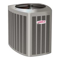
This EL22XPV outdoor air conditioner with all-aluminum
coil is designed for use with HFC-410A refrigerant only.
This unit must be installed with an approved indoor air han-
dler or coil. For AHRI Certied system match-ups and ex-
panded ratings, visit www.LennoxPros.com. The EL22XPV
variable capacity unit may be installed with an S30 com-
municating thermostat or a standard 24VAC non-communi-
cating heat pump thermostat. See eld wiring diagrams for
wiring details. These instructions are intended as a general
guide and do not supersede local codes in any way. Con-
sult authorities having jurisdiction before installation.
NOTICE!
Charging information is given on the charging
procedure sticker on the unit access panel. For more in-
depth information, consult the Installation and Service
Procedures manual on LennoxPros.com or through the
Technical Support department at 800-453-6669.
IMPORTANT: Special procedures are required for clean-
ing the all-aluminum coil in this unit. See page 21 in this
instruction for information.
See
NOTES
See NOTES
NOTES:
Service clearance of 30 in. (762 mm) must be maintained on one of
the sides adjacent to the control box.
Clearance to one of the other three sides must be 36 in (914 mm).
Clearance to one of the remaining two sides may be 12 in. (305mm)
and the final side may be 6 in.(152 mm).
A clearance of 24 in. (610 mm) must be maintained between two units.
48 in. (1219 mm) clearance required on top of unit.
See
NOTES
See NOTES
Control
Box
SETTING THE UNIT – Clearances
THIS MANUAL MUST BE LEFT WITH THE
HOMEOWNER FOR FUTURE REFERENCE
Question and Answer IconNeed help?

Do you have a question about the Lennox Elite EL22XPV-048 and is the answer not in the manual?

Lennox Elite EL22XPV-048 Specifications

General IconGeneral
ModelEL22XPV-048
TypeHeat Pump
Cooling Capacity48, 000 BTU
Heating Capacity48, 000 BTU
SEER Rating22
HSPF Rating10
Compressor TypeVariable Speed
RefrigerantR-410A
Heating StagesVariable
Capacity4 Ton
Voltage208/230V

Summary

Unit Placement Guidelines

Stabilizer Bracket Use

Emphasizes the use of stabilizers for elevated or unstable installations.

Refrigerant Piping Installation

Important Safety Warnings

Safety precautions for refrigerant handling, pressurization, and system integrity.

Heat Pump System Guidelines

Guidelines for total equivalent length, maximum linear length, and liquid lift for HFC410A systems.

Refrigerant Piping Details

Suction Trap Requirements

Requirements for installing suction traps based on unit elevation.

Indoor Metering Device Removal and Flushing

Metering Device Removal Procedures

Step-by-step guides to remove fixed orifice and expansion valve metering devices.

Flushing Procedure Setup

Instructions for connecting gauges and equipment for flushing the system.

Line Set Flushing

Detailed procedure for flushing the line set and indoor unit coil.

Refrigerant Piping Brazing Procedures

Gauge Set Attachment for Brazing

Connecting manifold gauges for brazing with nitrogen flow.

Brazing Process and Preparation

Brazing Steps and Cooling

Wrap valves, flow nitrogen, braze line set, and prepare for next steps, including cooling.

Indoor Expansion Valve Installation

Expansion Valve Installation Steps

Step-by-step guide for installing the expansion valve.

Leak Test and Evacuation Procedures

Performing the Leak Test

Detailed steps for performing a leak test on the system.

System Evacuation

Evacuating the System

Steps for evacuating the system to target micron levels.

Evacuation Safety Warning

Warning about potential equipment damage from deep vacuum operation.

Electrical Wiring and Circuit Sizing

Electrical Safety Warnings

Warnings on electric shock, aluminum wire fire hazard, and proper circuit sizing.

S30 Communicating Thermostat Wiring Diagram

Conventional Thermostat Wiring Diagrams

Outdoor Unitary Control Features

Charge Mode Operation

Function and operation of the Charge Mode Jumper for service.

Operation Mode Jumper Settings

Explanation of the Operation Mode Jumper settings for cooling modes.

Refrigerant Charge and System Information

Start-Up and Performance Checklist

System Refrigerant Charge Verification

Referencing information for required subcooling and approach temperatures.

Related product manuals