EasyManua.ls Logo

Lennox EL16XP1 Series

Lennox EL16XP1 Series
30 pages
To Next Page IconTo Next Page
Loading...
Page 1
WARNING
Improper installation, adjustment, alteration, service
or maintenance can cause property damage, personal
injury or loss of life. Installation and service must be
performed by a licensed professional HVAC installer or
equivalent, service agency, or the gas supplier.
IMPORTANT
The Clean Air Act of 1990 bans the intentional venting of
refrigerant (CFCs, HCFCs and HFCs) as of July 1, 1992.
Approved methods of recovery, recycling or reclaiming
must be followed. Fines and/or incarceration may be
levied for noncompliance.
IMPORTANT
This unit must be matched with an indoor coil as
specied in Lennox Product Specication bulletin. Coils
previously charged with HCFC-22 must be ushed.
CAUTION
As with any mechanical equipment, contact with sharp
sheet metal edges can result in personal injury. Take
care while handling this equipment and wear gloves and
protective clothing.
WARNING
Electric Shock Hazard. Can cause injury or
death. Unit must be properly grounded in
accordance with national and local codes.
Line voltage is present at all components when
unit is not in operation on units with single-
pole contactors. Disconnect all remote electric
power supplies before opening access panel.
Unit may have multiple power supplies.
EL16XP1
Table of Contents
Installation Clearances ...................................................2
Model Number Identication ...........................................2
Dimensions .....................................................................3
Specications .................................................................4
Typical Unit Parts Arrangement ...................................... 6
Operating Gauge Set and Service Valves ......................6
Unit Placement ..............................................................8
New or Replacement Line Set ........................................9
Brazing Connections ................................................... 11
Flushing Line Set and Indoor Coil ................................14
Installing Indoor Metering Device .................................15
Leak Test Line Set and Indoor Coil ..............................16
Evacuating Line Set and Indoor Coil ...........................17
Electrical .......................................................................18
System Operation .......................................................20
System Conguration ...................................................20
Defrost System ...........................................................23
Maintenance ...............................................................25
Wiring and Sequence of Operation ...........................27
Servicing Units Void of Charge ...................................29
Start-Up ......................................................................29
Service Literature
UNIT INFORMATION
Corp. 1819-L8
July 16, 2020
EL16XP1 (HFC-410A) SERIES OUTDOOR UNITS
General Information
These instructions are intended as a general guide and do
not supersede national or local codes in any way. Consult
authorities having jurisdiction before installation.
This EL16XP1 outdoor heat pump with all-aluminum coil
is designed for use with HFC-410A refrigerant only. This
unit must be installed with an approved indoor air handler
or coil. See the Lennox EL16XP1 Product Specications
bulletin (EHB) for approved indoor component match ups.
These instructions are intended as a general guide and do
not supersede local codes in any way. Consult authorities
having jurisdiction before installation.
This outdoor unit is designed for use in systems that use
the following refrigerant metering device:
Check thermal expansion valve (CTXV)
IMPORTANT: Special procedures are required for clean-
ing the all-aluminum coil in this unit. See page 25 in this
instruction for information.
Question and Answer IconNeed help?

Do you have a question about the Lennox EL16XP1 Series and is the answer not in the manual?

Lennox EL16XP1 Series Specifications

General IconGeneral
BrandLennox
ModelEL16XP1 Series
CategoryHeat Pump
LanguageEnglish

Summary

General Information and Specifications

Installation Clearances

Requirements for proper unit spacing and airflow.

Model Number Identification

Guide to understanding the unit's model number components.

Dimensions

Physical measurements of the outdoor unit for installation planning.

Specifications

Technical data including tonnage, refrigerant, electrical, and fan details.

Installation and Setup

Unit Components and Valve Operation

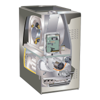
Overview of unit parts, service valves, and gauge usage.

Using Manifold Gauge Set

Guidelines for using manifold gauges with HFC-410A systems.

Operating Service Valves

Information on accessing and operating angle and ball type service valves.

Service Valve Types and Details

Detailed procedures for accessing and reinstalling service valve components.

To Access Service Port

Procedure for accessing the service port on angle and ball valves.

Reinstall Stem Cap

Steps for properly reinstalling stem caps on service valves.

Unit Placement and Mounting

Guidance on positioning the unit for optimal performance and safety.

Roof Mounting Considerations

Specific requirements for installing the unit on a roof.

Line Set Installation and Connections

Procedures for installing and connecting refrigerant line sets.

Line Set Installation Techniques

Illustrations showing proper methods for isolating refrigerant lines.

Brazing Connections

Safe and effective methods for brazing refrigerant line connections.

Flushing Line Set and Indoor Coil

Essential procedures for cleaning internal system components.

Installing Indoor Metering Device

Instructions for installing the expansion valve at the indoor coil.

Leak Test Line Set and Indoor Coil

Method for detecting leaks in the refrigerant system.

Evacuating Line Set and Indoor Coil

Procedure to remove air and moisture from the system.

Electrical and Wiring Installation

Guidance on electrical safety and wiring practices.

Service Disconnect Switch Installation

Requirements for installing the electrical disconnect switch.

Low-Voltage Wiring

Details on 24VAC transformer and thermostat placement.

Control Wiring Diagrams

Visual representation of standard control wiring configurations.

System Operation and Controls

System Operation Overview

Explanation of how the unit operates in cooling and heating modes.

Unit Components

Overview of key unit components and their functions.

Defrost System Operation

Explanation of defrost cycle initiation and operation.

System Configuration

Details on system configuration and demand defrost controls.

Defrost System Details

In-depth information on defrost controls and modes.

Emergency Heat Mode

Functionality of emergency heat mode and indicators.

Defrost System Overview

How the control determines defrost cycles based on ambient and coil temp.

Defrost Control Settings

Details on control inputs, outputs, and configurable settings.

Demand Defrost Control Diagnostic LEDs

Interpretation of diagnostic codes for the defrost control.

Operating Sequence

Step-by-step breakdown of unit operation modes.

Cooling Sequence

Step-by-step operation sequence for cooling mode.

Heating Sequence

Step-by-step operation sequence for heating modes.

Defrost Mode Sequence

Detailed sequence of operation during defrost mode.

Maintenance and Start-Up

Maintenance Procedures

Recommended tasks for maintaining the unit's performance and longevity.

Outdoor Unit Maintenance

Procedures for cleaning and inspecting the outdoor unit.

Indoor Unit Maintenance

Procedures for maintaining the indoor unit, including filters.

Homeowner Maintenance

Maintenance tasks that can be performed by the homeowner.

Thermostat and Heat Pump Operation

Guidance on thermostat use and heat pump operating characteristics.

Extended Power Outage

Procedures for handling extended power interruptions.

Preservice Check

Checks to perform before calling for service.

Servicing Units Void of Charge

Procedures for servicing units that have lost their refrigerant charge.

Start-Up and Performance Checklist

Final checks and verification before system operation.

Related product manuals