EasyManua.ls Logo

Lennox Elite EL18XPV Series - User Manual

Lennox Elite EL18XPV Series
22 pages
Print Icon
To Next Page IconTo Next Page
Loading...
©2021 Lennox Industries Inc.
Dallas, Texas, USA
Page 1
THIS MANUAL MUST BE LEFT WITH THE
HOMEOWNER FOR FUTURE REFERENCE
WARNING
Improper installation, adjustment, alteration, service
or maintenance can cause property damage, personal
injury or loss of life. Installation and service must be
performed by a licensed professional HVAC installer or
equivalent, or service agency.
IMPORTANT
The Clean Air Act of 1990 bans the intentional venting of
refrigerant (CFCs, HCFCs and HFCs) as of July 1, 1992.
Approved methods of recovery, recycling or reclaiming
must be followed. Fines and/or incarceration may be
levied for noncompliance.
CAUTION
As with any mechanical equipment, contact with sharp
sheet metal edges can result in personal injury. Take
care while handling this equipment and wear gloves and
protective clothing.
INSTALLATION
INSTRUCTIONS
HEAT PUMP
508059-01
1/2021
Elite
®
Series EL18XPV Units
PACKING LIST
OUTDOOR UNIT
WARRANTY
CERTIFICAT E
RAST 6-PIN
CONNECTORS (2)
General
This EL18XPV outdoor air conditioner with all-aluminum
coil is designed for use with HFC-410A refrigerant only.
This unit must be installed with an approved indoor air
handler or coil. For AHRI Certied system match-ups and
expanded ratings, visit www.LennoxPros.com. The EL18X-
PV variable capacity unit may be installed with an S30
iComfort communicating thermostat or a standard 24VAC
non-communicating heat pump thermostat. See eld wiring
diagrams for wiring details. These instructions are intend-
ed as a general guide and do not supersede local codes
in any way. Consult authorities having jurisdiction before
installation.
NOTICE!
Charging information is given on the charging
procedure sticker on the unit access panel. For more in-
depth information, consult the Installation and Service
Procedures manual on LennoxPros.com or through the
Technical Support department at 800-453-6669.
IMPORTANT: Special procedures are required for clean-
ing the all-aluminum coil in this unit. See page 21 in this
instruction for information.
See
NOTES
See NOTES
NOTES:
Service clearance of 30 in. (762 mm) must be maintained on one of
the sides adjacent to the control box.
Clearance to one of the other three sides must be 36 in (914 mm).
Clearance to one of the remaining two sides may be 12 in. (305mm)
and the final side may be 6 in.(152 mm).
A clearance of 24 in. (610 mm) must be maintained between two units.
48 in. (1219 mm) clearance required on top of unit.
See
NOTES
See NOTES
Control
Box
SETTING THE UNIT – Clearances
Question and Answer IconNeed help?

Do you have a question about the Lennox Elite EL18XPV Series and is the answer not in the manual?

Summary

Installation Safety and Warnings

General Installation Warning

Warning regarding improper installation, adjustment, alteration, service, or maintenance.

Refrigerant Handling Compliance

Information on the Clean Air Act and proper refrigerant recovery methods.

Installation Safety Precautions

Panel Handling and Storage Safety

Warnings and precautions for handling and storing unit panels during installation.

Exhaust Vent Impact on Unit

Warning about exhaust gases affecting unit performance and longevity.

Refrigerant Piping Requirements

Oil Type and System Flushing

Details on PVE oil usage and flushing procedures for older systems.

Refrigerant Handling Safety

Critical warnings regarding safe handling of refrigerants and potential hazards.

Refrigerant Piping Installation Steps

Removing Indoor Metering Devices

Procedures for removing fixed orifice and expansion valve devices.

Flushing Line Set Procedure

Detailed steps for flushing the refrigerant line set using HCFC-22.

Connecting Equipment for Flushing

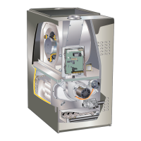
Diagram and instructions for connecting gauges and recovery machine.

Refrigerant Piping Brazing Procedures

Brazing Preparation and Safety

Steps for cutting, deburring, and preparing lines for brazing, including safety.

Manifold Gauge Set Connection for Brazing

Procedure for connecting manifold gauges and nitrogen for brazing.

Brazing Safety Warnings

Warnings about fire hazards and hazardous materials during brazing.

Brazing Line Set Connections

Wrapping Service Valves During Brazing

Instructions for protecting service valves with water-saturated cloths.

Cooling Brazed Joints

Procedure for cooling brazed joints after completion to protect valve seals.

Preparing for Next Installation Step

Steps after brazing, including disconnecting gauges and cooling pipes.

Indoor Expansion Valve Installation

Installing the Expansion Valve Unit

Steps for connecting the expansion valve to the indoor coil's orifice housing.

Sensing Bulb Installation and Positioning

Guidance on correctly installing and positioning the sensing bulb.

Equalizer Line Connection

Instructions for connecting the equalizer line to the check expansion valve.

Leak Testing and Evacuation

Connecting Gauge Set for Leak Test

Procedure for connecting the manifold gauge set to the system for testing.

Performing the Leak Test

Steps for pressurizing the system with nitrogen and checking for leaks.

Leak Test Warning

Warning regarding potential damage from deep vacuum operation.

System Evacuation Procedure

Connecting Gauge Set for Evacuation

Connecting the vacuum pump and gauges for system evacuation.

Evacuating to Target Vacuum Levels

Steps for reaching and verifying the required vacuum levels.

Evacuation Safety Warning

Warning about potential equipment damage and warranty voidance from improper evacuation.

Outdoor Unit Control Features

Unit Operation Modes Explained

Unit Start-Up Procedures

Refrigerant Charge Management

System Service and Maintenance

Start-Up and Performance Checklist

Overview

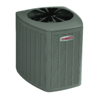
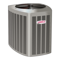
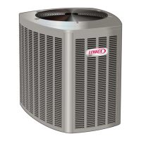
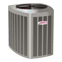
This document provides comprehensive installation and maintenance instructions for the Lennox Elite® Series EL18XPV Heat Pump units, designed for residential and light commercial HVAC applications. The EL18XPV is a variable-capacity outdoor unit that utilizes HFC-410A refrigerant and is intended for use with approved indoor air handlers or coils.

Function Description:

The Lennox Elite® Series EL18XPV Heat Pump is a variable-capacity cooling and heating system. It is designed to provide efficient temperature control by adjusting its compressor capacity based on demand. This unit can be integrated into two primary control systems:

  • iComfort S30 Communicating Thermostat Control: When paired with an iComfort S30 Ultra Smart Communicating Thermostat and an iComfort-enabled indoor unit, the EL18XPV operates as a fully communicating system. In this configuration, the unit's capacity is continuously varied from minimum to maximum based on thermostat demand, and the indoor air volume is precisely matched to the cooling capacity. This setup leverages advanced diagnostics, Wi-Fi accessibility, and system operation parameters for optimal performance.
  • Conventional 24VAC Non-Communicating Thermostat Control: The EL18XPV can also be installed with a conventional 24VAC non-communicating two-stage or single-stage heat pump thermostat. In this mode, the compressor capacity is controlled to maintain a target suction pressure setpoint. For two-stage thermostats, a Y1 demand initiates first-stage operation, and a Y2 demand (if sustained for 20 minutes) ramps up the compressor to maximum capacity. For single-stage thermostats, a jumper is installed between Y1 and Y2 on the outdoor control, and the compressor capacity varies to meet the suction pressure setpoint. The outdoor control incorporates advanced algorithms using the suction pressure sensor to achieve true variable capacity operation even with conventional thermostats.

The unit includes a "Charge Mode" function, activated by installing a jumper on the Charge Mode Pins, which forces the compressor and outdoor fan motor to operate at 100% capacity. This mode is essential for charging the system with refrigerant, checking the refrigerant charge, pumping down the system, and performing other service procedures. This mode has a maximum duration of 60 minutes, after which it automatically exits if the jumper is left in place.

A key component of the heat pump's functionality is its defrost operation. The master control continuously monitors differential temperatures to detect frost buildup on the outdoor coil, which can impair system performance. It self-calibrates and uses ambient and outdoor coil temperatures, along with total run-time, to determine when a defrost cycle is necessary. During a defrost cycle (typically 5 to 15 minutes), the system clears frost from the outdoor coil, and it is normal to observe steam rising from the unit. Auxiliary heat may engage during defrost to maintain indoor comfort.

Usage Features:

  • Refrigerant Piping: The unit is designed for use with HFC-410A refrigerant. Specific instructions are provided for flushing existing line sets and indoor coils, especially if they were previously charged with mineral oil or HCFC-22, to prevent contamination and ensure proper heat transfer. Polyvinyl ether (PVE) and polyol ester (POE) oils are used in Lennox variable-capacity units. Detailed guidelines are given for sizing refrigerant lines based on total equivalent length, with recommendations for line sets up to 150 linear feet. For longer runs (up to 180 feet total equivalent length), specific line set models and field-fabricated options are outlined, along with requirements for suction traps when the outdoor unit is elevated above the indoor unit.
  • Metering Device Installation: The EL18XPV requires an expansion valve metering device, purchased separately, at the indoor coil. Instructions cover the removal of existing fixed orifices or expansion valves and the installation of the new expansion valve, including proper placement of Teflon® rings, tightening procedures, and sensing bulb installation on the vapor line.
  • Leak Testing and Evacuation: A rigorous procedure is detailed for leak testing the line set and indoor unit using a trace amount of HFC-410A and nitrogen. Subsequent evacuation to an absolute pressure of 500 microns (29.9 inches of mercury) within a 20-minute period is critical to ensure a dry and leak-free system.
  • Electrical Connections: Wiring must comply with national and local electrical codes. The unit requires a 24VAC transformer (minimum 40 VA) for low-voltage control. Detailed wiring diagrams are provided for both iComfort communicating and conventional 24VAC non-communicating thermostat setups, including the use of RAST 6-Pin connectors for field wiring. Specific instructions are given for routing high and low voltage wiring, ensuring proper grounding, and maintaining appropriate wire gauges based on run length.
  • Unit Start-Up: Before initial start-up, it is important to energize the crankcase heater (if equipped) for 24 hours to prevent compressor damage. Checks include rotating the fan for binding, inspecting wiring connections, opening service valve stems, replacing stem caps, verifying voltage supply, and setting the thermostat for a cooling demand.
  • Charging: The unit is factory-charged for a 15-foot refrigerant piping length. Additional charge calculations are provided for longer line sets. Charging should be performed using the "Charge Mode" to ensure the unit operates at 100% capacity, and the charge should be verified using the subcooling and approach temperatures specified on the unit's charging sticker.

Maintenance Features:

  • Homeowner Maintenance: Homeowners are advised to schedule annual inspections and maintenance with a licensed HVAC technician before each heating and cooling season. Regular checks include inspecting and replacing indoor unit filters monthly, checking the indoor unit drain line for obstructions, and removing any obstructions around the outdoor unit to ensure proper airflow. Trimming shrubbery around the unit and keeping snow levels below the louvered panels during winter are also recommended.
  • Professional Maintenance: Licensed HVAC technicians should perform comprehensive checks twice a year. These include:
    • Outdoor Unit: Inspecting wiring, checking outdoor fan and blade condition, cleaning base pan drains, inspecting refrigerant piping for rubbing or insulation damage, testing capacitors, checking contactor contacts, inspecting outdoor fan motor bearings, and cleaning outdoor coils. Special care is required for cleaning all-aluminum coils, using potable water at moderate pressure (less than 50 psi) or a coil cleaner with a pH between 5 and 9, followed by thorough rinsing. In coastal areas, coils should be cleaned several times a year to prevent corrosive buildup.
    • Indoor Unit (Air Handler or Furnace): Inspecting wiring, checking and replacing air filters, cleaning the indoor blower, inspecting indoor coil drain pans and condensate drains, inspecting and cleaning the indoor coil, checking refrigerant lines for rubbing or insulation damage, inspecting the duct system for leaks, and checking indoor blower motor bearings. For systems with auxiliary gas or oil-fired furnaces, the technician should also inspect and clean burners, the gas valve, heat exchanger, and flue system.
  • General System Test: After maintenance, the technician should perform a general system test to verify operating functions, check for unusual noises or odors, measure indoor/outdoor temperatures and system pressures, and confirm the refrigerant charge. They should also verify system total static pressure and airflow settings, and check the temperature drop across the indoor coil.

The manual emphasizes safety warnings throughout, including precautions against improper installation, electrical shock, fire hazards, refrigerant inhalation, and electrostatic discharge (ESD) to protect electronic components. It also highlights the importance of using copper wire only and properly sizing wiring and circuit breakers.

Lennox Elite EL18XPV Series Specifications

General IconGeneral
Compressor TypeVariable Speed
RefrigerantR-410A
Energy Star CertifiedYes
StagesVariable
ClimateAll Climates
HSPF10
Smart TechnologyiComfort-enabled technology
Warranty10-Year Limited Warranty on covered components
SEERUp to 18

Related product manuals