Page 10
HEATING COMPONENTS
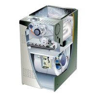
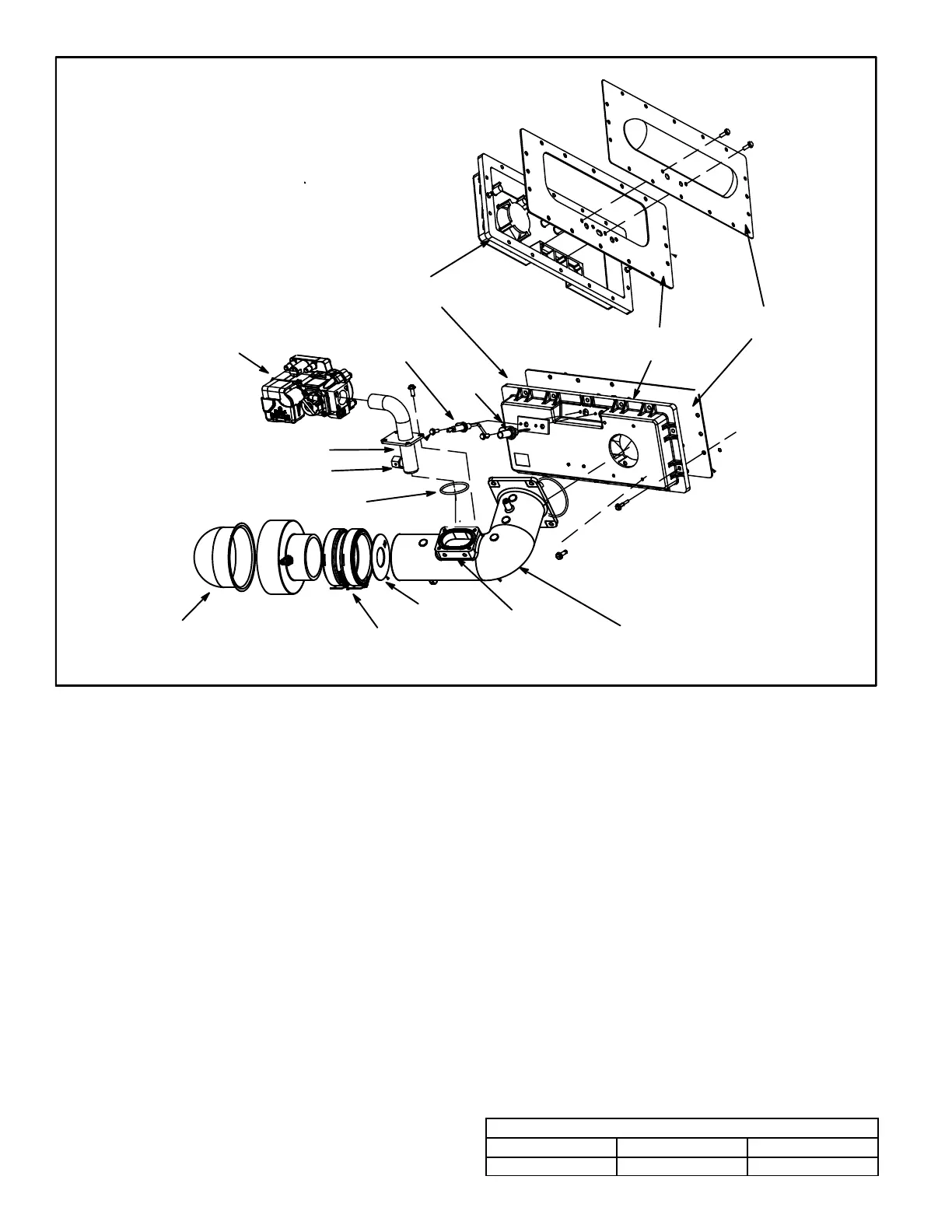
FIGURE 6
Air Gas Plenum
Burner
Gasket
Orifice Housing
Gas Valve
Air Orifice
Sensor
Ignitor
Gas Orifice
Thermal
Switch
(location)
Intake Air Screen
Intake Air
Elbow
Coupling
O Ring
5. Thermal Switch (Figure 6)
The auto-reset switch is located on the front of the intake air
elbow. The switch will safely shut the unit down if excessive
temperatures are detected. When the switch senses ex
cessive temperature, the circuit breaks and the ignition
control immediately stops ignition and closes the gas
valve.
6. Primary Limit Control
The primary limit (S10) is located in the heating vestibule
panel. When excess heat is sensed in the heat exchanger,
the limit will open. If the limit is open, the furnace control en
ergizes the supply air blower and closes the gas valve. The
limit automatically resets when unit temperature returns to
normal. The switch must reset within three minutes or the
SureLight control will go into Watch guard for one hour. The
switch is factory set and cannot be adjusted. The switch
may have a different set point for each unit model number.
See Lennox Repair Parts Handbook if limit switch must be
replaced.
7. Gas Valve (Figure 6)
The valve is internally redundant to assure safety shut-off.
If the gas valve must be replaced, the same type valve must
be used.
24VAC terminals and gas control knob are located on the
valve. A wire harness connects the terminals from the gas
valve to the electronic ignition control. 24V applied to the
terminals energizes the valve. Inlet and outlet pressure
taps are located on the valve. A regulator adjustment screw
is located on the valve.
EL180UHN units are equipped with a Honeywell gas valve
rated for ambient temperatures between -40º F and +175º
F.
8. Flame Sensor (Figure 6)
A flame sensor is located on the top of the air gas plenum.
The sensor can be removed for service without removing
the the burner. During operation, flame is sensed by cur
rent passed through the flame and sensing electrode. The
SureLight control allows the gas valve to remain open as
long as flame signal is sensed. To check flame sense signal
use the push-button found on the integrated control and go
to Field Test Mode. The menu will display the flame signal.
See Table 15 for flame signal.
TABLE 5
Flame Signal in Microamps
Normal Low Drop Out
1.5 or greater 0.5 - 1.4 0.4 or less
 Loading...