Page 11
9. Combustion Air Inducer (B6)
All EL180UHNE units use a combustion air inducer to
move air through the burners and heat exchanger during
heating operation. The blower uses a 120VAC motor. The
motor operates during all heating operation and is con
trolled by integrated control A92. The inducer also oper
ates for 15 seconds before burner ignition (pre‐purge) and
for 5 seconds after the gas valve closes (post‐purge).
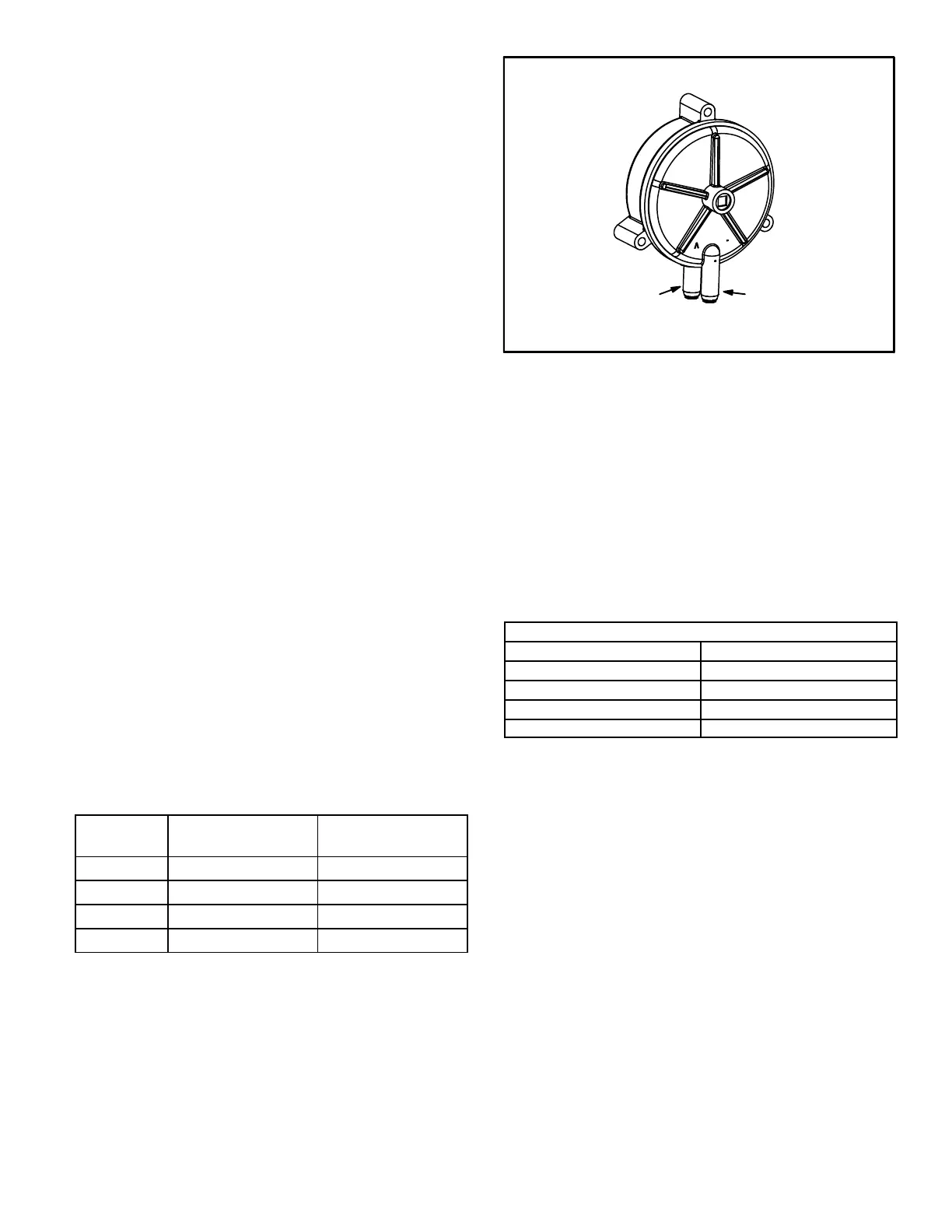
10. Combustion Air Inducer Prove Switch (S18)
EL180UHNE series units are equipped with a combustion
air pressure switch (figure 7) located near the gas valve. The
switch is connected to the combustion air inducer housing
by means of a flexible silicone hose. It monitors negative air
pressure in the intake air elbow.
The switch is a single‐pole single‐throw proving switch elec
trically connected to the furnace control. The purpose of the
switch is to prevent burner operation if the combustion air in
ducer is not operating or if the flue becomes obstructed.
On heat demand the switch senses that the combustion air
inducer is operating. It closes a circuit to the integrated con
trol when pressure inside the combustion air inducer de
creases to a certain set point. The pressure sensed by the
switch is negative relative to atmospheric pressure. If the
flue becomes obstructed during operation, the switch
senses a loss of pressure difference and opens the circuit
to the furnace control and gas valve. See table 6 for set
point.
If replacing the inducer switch or tubing is necessary, make
note of the tubing connections to the gas valve. See figure
8.
NOTE - The switch is factory set and is not field adjustable.
It is a safety shut‐down control in the furnace and must not
be by-passed for any reason. If switch is closed or by-
passed, the control will not initiate ignition at start up.
TABLE 6
Prove Switch Set Points
EL180
Model
Make inches w.c. Break inches w.c.
040 0.35 0.20
060 0.35 0.20
080 0.35 0.20
100 0.35 0.20
FIGURE 7
COMBUSTION AIR PRESSURE SWITCH
Positive +
to air intake pipe
Negative -
to air intake
elbow
11. Burner and Orifice
Burners are factory set and require no adjustment. Always
operate the unit with air gas plenum in place. The burner
has one orifice located between the gas valve and the air
intake assembly (Figure 6). To check or replace the orifice
remove the intake air screen, coupling and intake air elbow.
Using a 5/8” socket, go through the elbow and unscrew the
gas orifice. The burner uses an orifice (see Table 7) that is
precisely matched to the burner input. The burner can be
removed for service. If burner has been removed, it is criti
cal to replace all gaskets.
TABLE 7
Gas Orifice Nat Gas
Unit Input Orifice Size
40 0.0595
60 0.0595
80 0.0689
100 0.0810
12. Ignitor (Figure 6)
The SureLight® ignitor is made of durable silicon nitride. Ig
nitor longevity is enhanced by controlling voltage to the ig
nitor. The integrated control provides a regulated 120 volts
to the ignitor for a consistent ignition and long ignitor life.
Ohm value should be 39 to 70.
See figure 9 for resistance, and voltage check.
NOTE - The EL180UHNE furnace contains electronic
components that are polarity sensitive. Make sure that the
furnace is wired correctly and is properly grounded.
 Loading...