Page 44
Gas Pressure Adjustment
Gas Flow (Approximate)
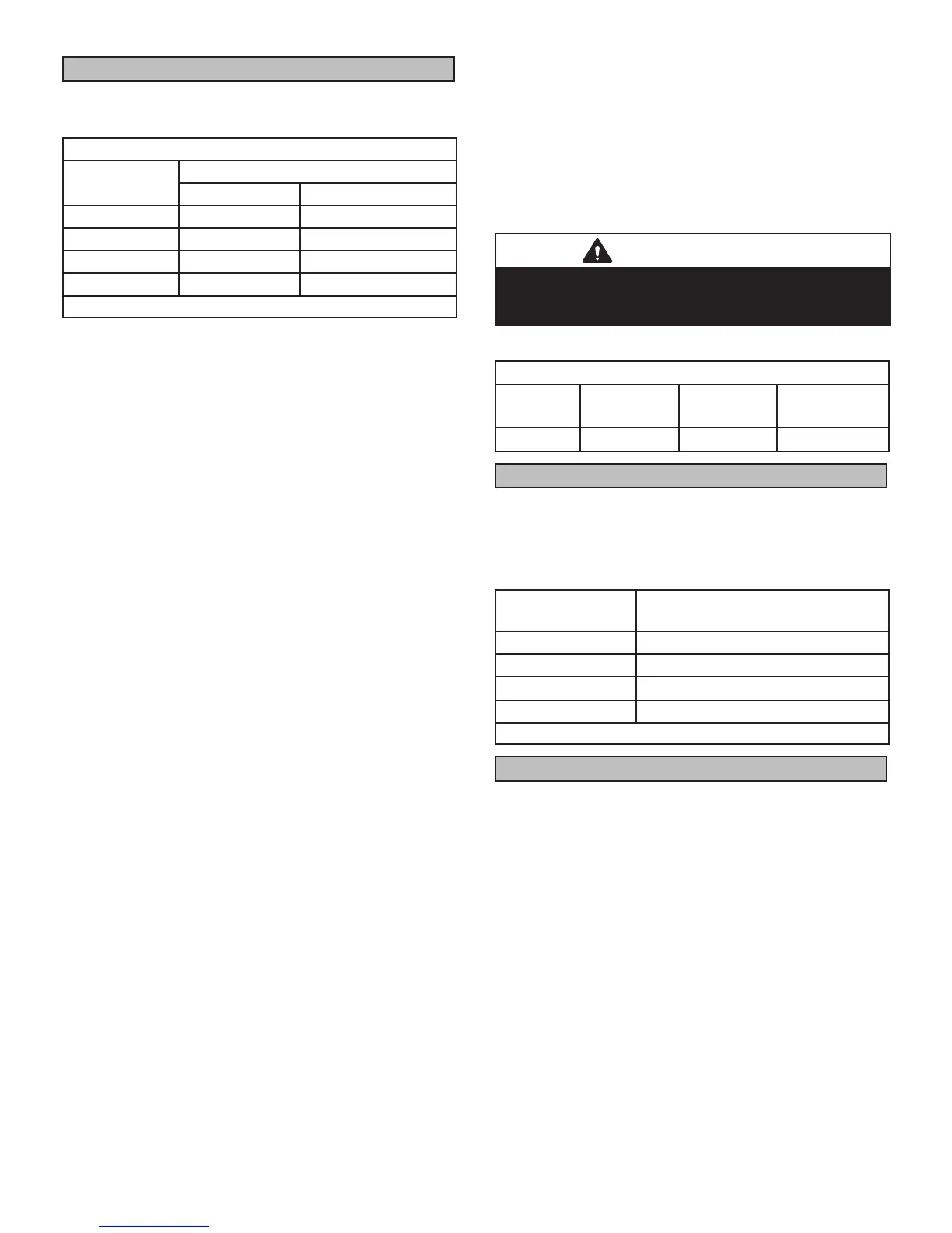
TABLE 12
GAS METER CLOCKING CHART
EL195 Unit
Seconds For One Revolution
1 cu ft Dial 2 cu ft Dial
-040 90 180
-060 60 120
-080 45 90
-100 36 72
Natural-1000 btu/cu ft
Furnace should operate at least 5 minutes before check-
ing gas ow. Determine time in seconds for two revolu-
tions of gas through the meter. (Two revolutions assures a
more accurate time.) Divide by two and compare to time
in table 12 below. If manifold pressure matches table 13
and rate is incorrect, check gas orices for proper size and
restriction. Remove temporary gas meter if installed.
NOTE - To obtain accurate reading, shut off all other gas
appliances connected to meter.
Supply Pressure Measurement
A threaded plug on the inlet side of the gas valve provides
access to the supply pressure tap. Remove the threaded
plug, install a eld-provided barbed tting and connect a
manometer to measure supply pressure.
On multiple unit installations, each unit should be checked
separately, with and without units operating. Supply pres-
sure must fall within range listed in table 13.
Check Manifold Pressure
To correctly measure manifold pressure, follow the steps
below
1 - Remove the threaded plug from the outlet side of
the gas valve and install a eld-provided barbed
tting. Connect measuring device “+” connection to
barbed tting to measure manifold pressure.
2 - Start unit and allow 5 minutes for unit to reach steady
state.
3 - After allowing unit to stabilize for 5 minutes, record
manifold pressure and compare to value given in
Table 18.
4 - Shut unit off and remove manometer as soon as an
accurate reading has been obtained. Take care to
remove barbed tting and replace threaded plug.
5 - Start unit and perform leak check. Seal leaks if found.
IMPORTANT
For safety, connect a shut-off valve between the
manometer and the gas tap to permit shut off of gas
pressure to the manometer.
TABLE 13
Supply Line and Manifold Pressure (inches w.c.)
Unit Fuel
Manifold
Pressure
Line Pressure
All Nat 3.5 4.5 - 10.5
Proper Combustion
Furnace should operate minimum 15 minutes with correct
manifold pressure and gas ow rate before checking com-
bustion. Take combustion sample beyond the ue outlet
and compare to the tables below.
TABLE 14
EL195
Model
CO
2
% For Nat
040 6.3 - 7.8
060 6.5 - 8.2
080 7.2 - 8.4
100 7.3 - 8.5
The maximum carbon monoxide reading should not exceed 100ppm.
High Altitude Information
Units are NOT approved for installations over 4500 ft.

 Loading...