Page 40
Manifold and Signal Pressure Measurement
To correctly measure manifold and signal pressure, follow
the steps below:
1 - Turn o the electrical power and gas supply to the
furnace.
2 - Remove the threaded plug from the outlet side of
the gas valve and install a eld-provided barbed
tting. Connect measuring device positive “+” to
barbed tting to measure manifold pressure. See
gure 52 for manifold location.
3 - Install hoses and meter as shown in gure 56 for
signal pressure measurement.
4 - After allowing unit to stabilize for 8 minutes, record
manifold pressure and compare to value in table 18.
If manifold pressure is within range, rate check is
complete move to step 6. If manifold pressure is not
within range continue. Valve is not adjustable. Do
not adjust manifold pressure.
5 - Record signal pressure and compare to value in table
18. If signal pressure is within range continue. If the
signal is not within range go to “Troubleshooting”.
6 - Shut o unit and remove manometer and signal
meter after accurate readings has been obtained.
7 - Restart unit and check for gas leaks. Seal any leaks
found.
If the unit has diculty igniting or ignites with loud
resonance the air orice must be checked and re-
placed if necessary.
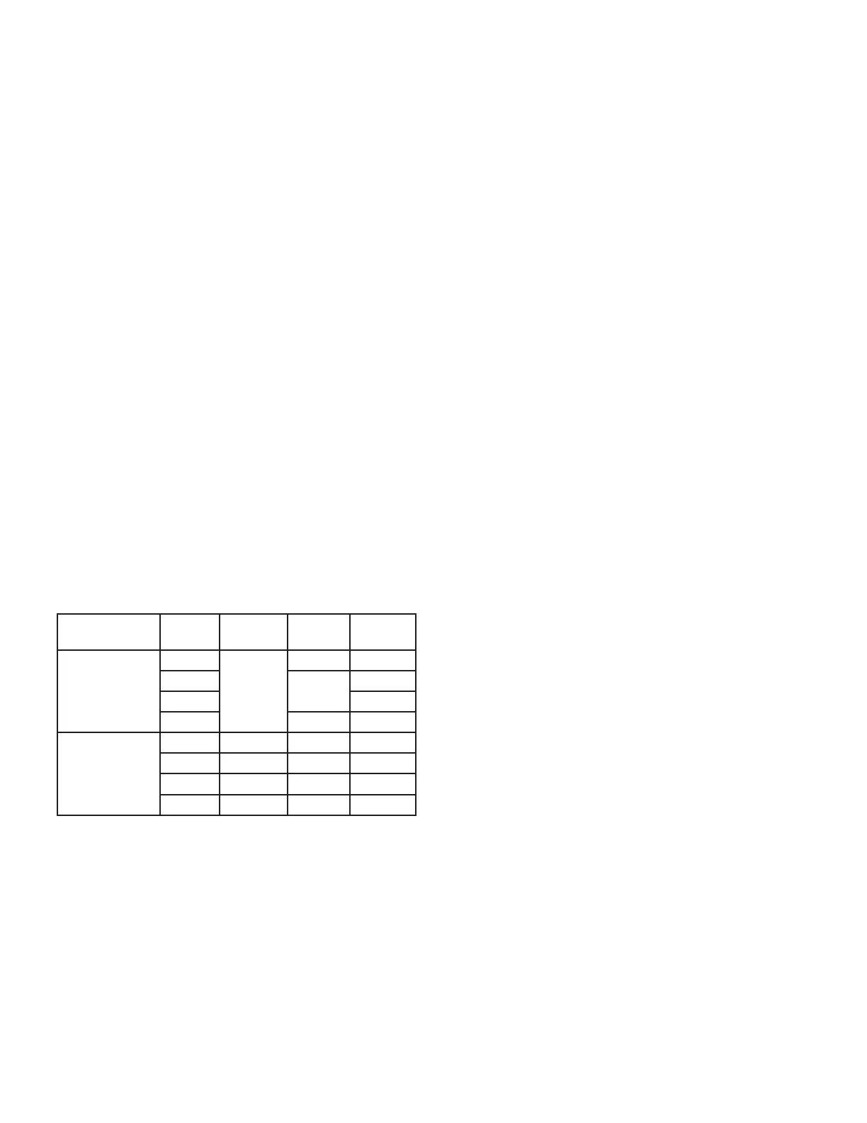
TABLE 18
Manifold and Signal Pressure (inches w.c.)
Altitude Unit
Natural
Manifold
Propane
Manifold
Signal
0 - 4500 ft
-040
3.2 - 3.8
n/a 0.80-0.93
-060
3.6
0.69-0.93
-080 0.73-0.93
-100 n/a 0.75-0.82
4501 - 7500 ft
-040 3.2 n/a 0.78-0.82
-060 2.3 2.5 0.55-0.62
-080 2.4 2.8 0.58-0.62
-100 2.3 n/a
0.55-0.60
Air Orice Replacement
Do not replace the air orice until the problem has been
determined. If the unit has diculty igniting the orice is
oversized and brings in too much air. If the unit ignites
but with loud resonance the orice is too small and needs
more air. The air orice is located inside the gray coupling
between the clamps. Figure 55 show corresponding steps
with the steps below.
1 - Turn o the electrical power and gas supply to the
furnace.
2 - Remove the black air pressure tube on the air intake
coupling.
3 - Use a 5/16” nut driver to loosen the clamps on the
gray coupling.
4 - Remove the two screws attaching the air intake
coupling to the furnace cabinet.
5 - Remove the air intake coupling. If the air intake
coupling is still too dicult to remove, then remove
the two screws from the right side of the top cap
and one from the far right side of the blower deck
that attaches to the cabinet. See gure 54. Carefully
pull cabinet side away from air intake coupling, then
remove the air intake coupling. Note: Be careful not
to bend the cabinet side.
6 - Remove the air orice. Check the “Part” number
stamped on the air orice. See table 19. If the part
number is incorrect, then replace it with the proper
air orice. Repeat manifold check. If air orice
is correct diameter, then it must be replaced to
resolve ignition or resonance issue. See table 19
for replacement.
7 - Reinstall the air orice on the left side of the coupling
and push rmly into place.
8 - Reinstall air intake coupling making sure it is fully
seated in the gray coupling. Re-install the two
screws attaching the air intake coupling to the
furnace cabinet. Tighten clamps to secure the
coupling. Re-install the two screws on the right side
of the top cap and the one screw that attaches the
blower deck to the cabinet.
9 - Reconnect the black air pressure tube.
10 - Repeat manifold and signal pressure check. If
unit ignites and manifold and signal pressure are
correct, move on to combustion check. If unit still
does not ignite or ignites with loud resonance go to
Troubleshooting gure 57.

 Loading...