Page 39
IV-HEATING SYSTEM SERVICE CHECKS
A-C.S.A. Certication
All units are C.S.A. design certied without modications.
Refer to the EL195UHNE Operation and Installation In-
struction Manual Information.
B-Gas Piping
CAUTION
If a exible gas connector is required or allowed by
the authority that has jurisdiction, black iron pipe
shall be installed at the gas valve and extend outside
the furnace cabinet. The exible connector can then
be added between the black iron pipe and the gas
supply line.
WARNING
Do not over torque (800 in-lbs) or under torque (350
in-lbs) when attaching the gas piping to the gas
valve.
Gas supply piping should not allow more than 0.5” W.C.
drop in pressure between gas meter and unit. Supply gas
pipe must not be smaller than unit gas connection.
Compounds used on gas piping threaded joints should be
resistant to action of liqueed petroleum gases.
C-Testing Gas Piping
IMPORTANT
In case emergency shutdown is required, turn o the
main shut-o valve and disconnect the main power
to unit. These controls should be properly labeled
by the installer.
When pressure testing gas lines, the gas valve must be
disconnected and isolated. Gas valves can be damaged if
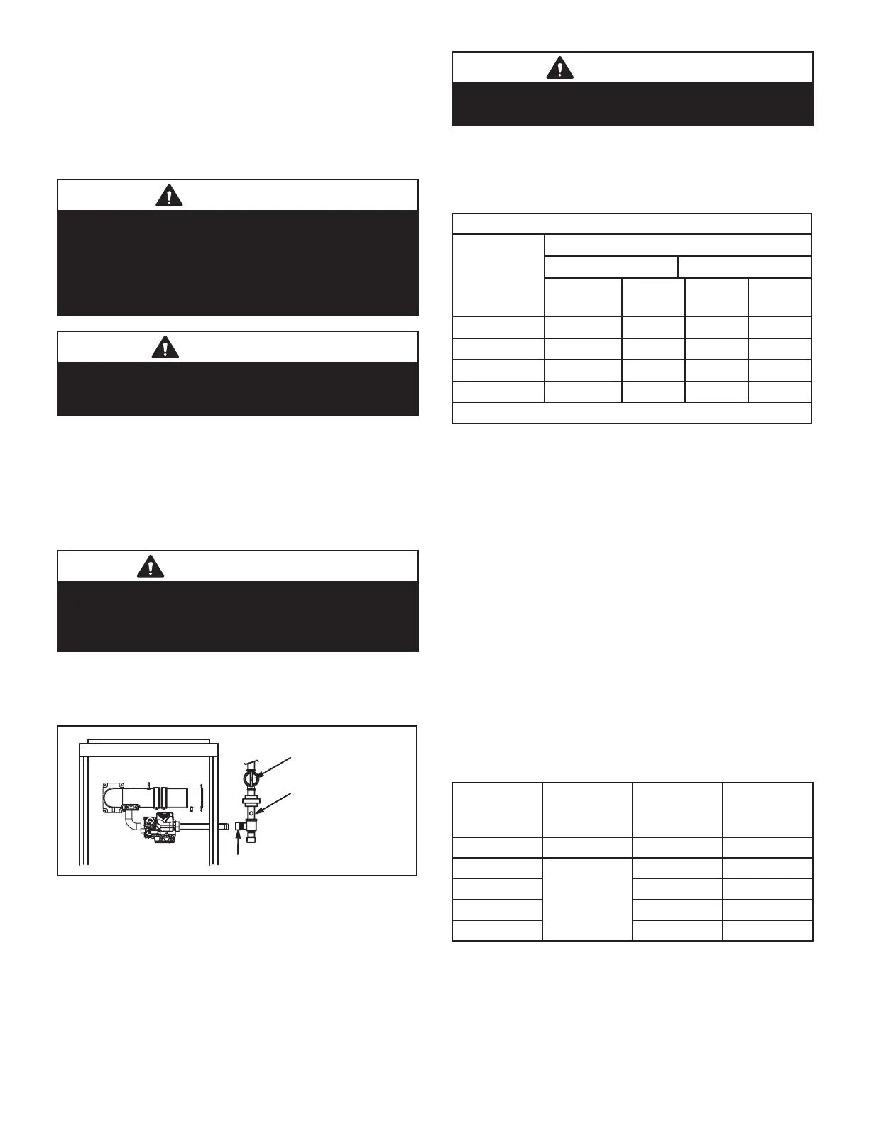
subjected to more than 0.5 psig (14” W.C.). See gure 53.
Isolate Gas Valve
Manual Main Shut-Off Valve Will
Not Hold Normal Test Pressure
1/8” N.P.T.
Plugged Tap
FIGURE 53
When checking piping connections for gas leaks, use
preferred means. Kitchen detergents can cause harmful
corrosion on various metals used in gas piping. Use of a
specialty Gas Leak Detector is strongly recommended. It
is available through Lennox under part number 31B2001.
See Corp. 8411-L10, for further details.
WARNING
Do not use matches, candles, ame or any other
source of ignition to check for gas leaks.
D-Gas Supply, Manifold and Signal Pressure
Gas Flow (Approximate)
TABLE 16
GAS METER CLOCKING CHART
EL195E
Model
Seconds For One Revolution
Natural
LP/Propanae
1 cu ft
Dial
2 cu ft
Dial
1 cu ft
Dial
2 cu ft
Dial
-040
90 180 n/a n/a
-060 60 120 150 300
-080 45 90 112 224
-100 36 72 n/a n/a
Natural-1000 btu/cu ft / Propane 2500 btu/cu ft
Furnace should operate at least 5 minutes before check-
ing gas ow. Determine time in seconds for two revolu-
tions of gas through the meter. (Two revolutions assures a
more accurate time.) Divide by two and compare to time in
table 16. If manifold pressure matches table 18 and rate is
incorrect, check gas orices for proper size and restriction.
Remove temporary gas meter if installed.
NOTE - To obtain accurate reading, shut o all other gas
appliances connected to meter.
Supply Pressure Measurement
A threaded plug on the inlet side of the gas valve provides
access to the supply pressure tap. Remove the thread-
ed plug, install a eld-provided barbed tting and connect
a manometer to measure supply pressure. Replace the
threaded plug after measurements have been taken. See
table 17 for supply line pressure.
On multiple unit installations, each unit should be checked
separately, with and without units operating.
TABLE 17
Supply Line
Unit Fuel
Supply Line
WC”
Propane Kit
0-7500ft
(0-1372m)
All Nat 4.5 - 10.5
-040
LP/Propane
N/A N/A
-060 11.0 - 13.0 19K05
-080 11.0 - 13.0 19K06
-110 N/A N/A
NOTE - A natural to L.P. propane gas changeover kit is necessary to convert this
unit. Refer to the changeover kit installation instruction for the conversion proce-
dure and manifold pressure measure procedure.
E- High Altitude
Units may be installed at altitudes up to 7,500 ft. above
sea level. See Table 18 for de-rate manifold values.

 Loading...