Page 24
Vent Piping Guidelines
NOTE - Lennox has approved the use of DuraVent
®
and
Centrotherm manufactured vent pipe and terminations as
an option to PVC. When using the PolyPro
®
by DuraVent or
InnoFlue
®
by Centrotherm venting system the vent pipe re
quirements stated in the unit installation instruction – mini
mum & maximum vent lengths, termination clearances,
etc. – apply and must be followed. Follow the instructions
provided with PoyPro by DuraVent and InnoFlue by Cen
trotherm venting system for assembly or if requirements
are more restrictive. The PolyPro by Duravent and In
noFlue by Centrotherm venting system must also follow
the uninsulated and unconditioned space criteria listed in
table 15.
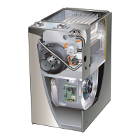
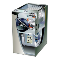
The EL196UHE can be installed as either a Non-Direct
Vent or a Direct Vent gas central furnace.
NOTE - In Non‐Direct Vent installations, combustion air is
taken from indoors and flue gases are discharged outdoors.
In Direct Vent installations, combustion air is taken from out
doors and flue gases are discharged outdoors.
Intake and exhaust pipe sizing -- Size pipe according to ta
bles 12 and
13. Count all elbows in side and outside the
home. Table 12 lists the minimum vent pipe lengths permit
ted. Table
13 lists the maximum pipe lengths permitted.
Regardless of the diameter of pipe used, the standard roof
and wall terminations described in section Exhaust Piping
Terminations should be used. Exhaust vent termination
pipe is sized to optimize the velocity of the exhaust gas as
it exits the termination. Refer to table 16.
In some applications which permit the use of several differ
ent sizes of vent pipe, a combination vent pipe may be
used. Contact Lennox' Application Department for assis
tance in sizing vent pipe in these applications.
NOTE - The exhaust collar on all models is sized to ac
commodate 2” Schedule 40 vent pipe. In horizontal appli
cations, any transition to exhaust pipe larger than 2” must
be made in vertical runs of the pipe. Therefore a 2” elbow
must be added before the pipe is transitioned to any size
larger than 2”. This elbow must be added to the elbow
count used to determine acceptable vent lengths. Con
tact the Application Department for more information
concerning sizing of vent systems which include multiple
pipe sizes.
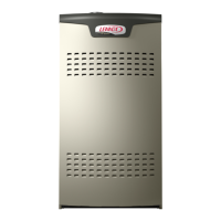
FIGURE 24
12” max
of straight pipe
Exhaust Pipe
12” Min.
NOTE - Exhaust pipe MUST be glued to furnace exhaust fittings.
NOTE - All horizontal runs of exhaust pipe must slope back to
ward unit. A minimum of 1/4” (6mm) drop for each 12” (305mm)
of horizontal run is mandatory for drainage.
NOTE - Exhaust piping should be checked carefully to make
sure there are no sags or low spots.
Horizontal Application
TABLE 12
MINIMUM VENT PIPE LENGTHS
EL196UHE
MODEL
MIN. VENT LENGTH*
030, 045, 070, 090, 110
15 ft. or
5 ft. plus 2 elbows or
10 ft. plus 1 elbow
*Any approved termination may be added to the minimum length listed.
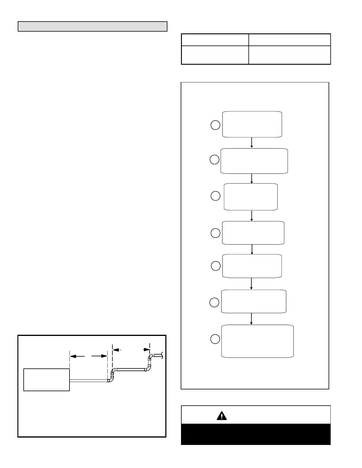
Use the following steps to correctly size vent pipe diameter.
FIGURE 25
Piping Size Process
1
2
3
4
5
6
Which style termination
being used?
Standard or concentric?
See table 11.
Which needs
most elbows?
Intake or
exhaust?
How many elbows?
Count all elbows inside
and outside house.
Desired pipe size?
Use table 13 or 14 to find
max intake or exhaust pipe
length. Includes all vent
pipe and elbows inside
and outside the house.
What is the altitude of
the furnace installation?
7
What is the
furnace capacity?
045, 070, 090,
110?
IMPORTANT
Do not use screens or perforated metal in exhaust or
intake terminations. Doing so will cause freeze-ups
and may block the terminations.
 Loading...