I
WARNING
Wiring must conform to the current National Electric Code
ANSI/NFPA No. 70, or Canadian Electric Code Part I,
CSA Standard C22,1, and local building codes. Refer to
the following wiring diagrams. See the unit nameplate for
minimum circuit ampacity and maximum overcurrent
)rotection size.
Select the proper supply circuit conductors according to
tables 310-16 and 310-17 in the National Electric Code,
ANSI/NFPA No, 70 or tables 1 through 4 in the Canadian
Electric Code, Part I, CSA Standard C22,1.
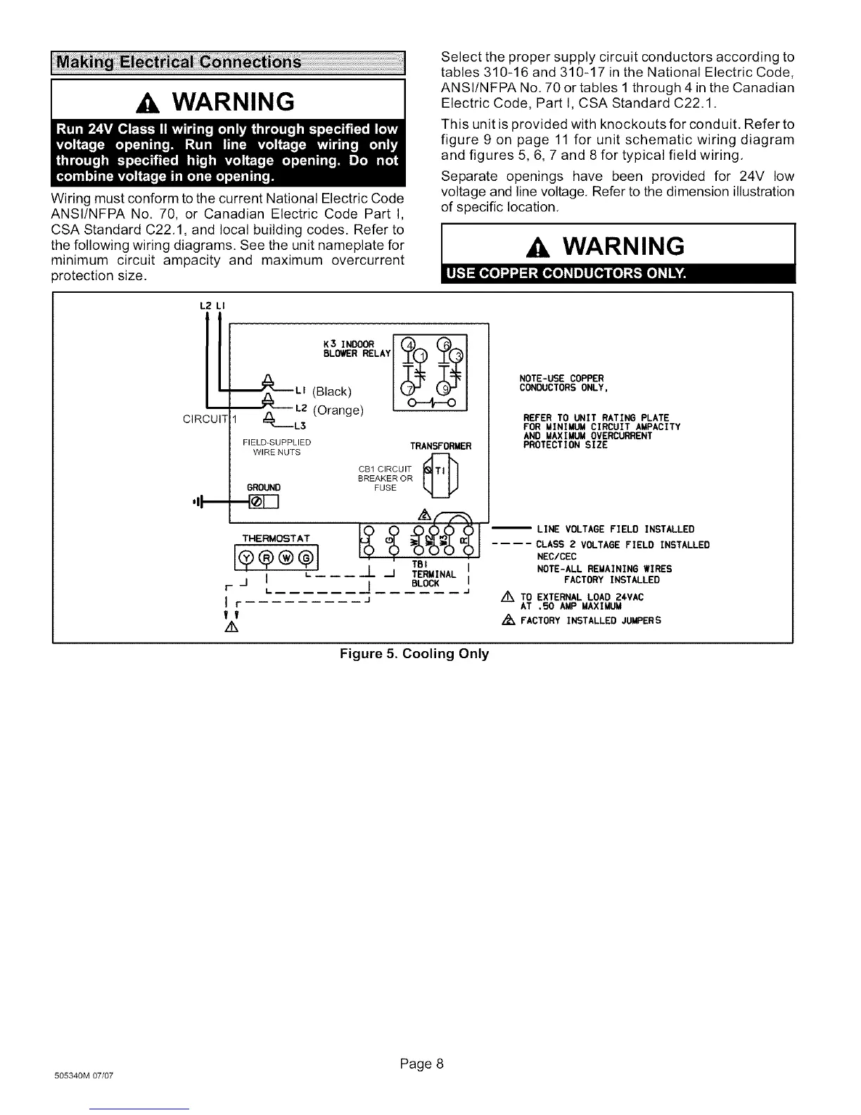
This unit is provided with knockouts for conduit. Refer to
figure 9 on page 11 for unit schematic wiring diagram
and figures 5, 6, 7 and 8 for typical field wiring.
Separate openings have been provided for 24V low
voltage and line voltage. Refer to the dimension illustration
of specific location.
L2 LI
CIRCUIT
,II--
K3 INDOOR I __
BLOWER RELAY
_LI (Black)
_LZ (Orange)
#m---L3
FIELD-SUPPLIED
WIRE NUTS
GROUND
THERMOSTAT
_1 I L
Ir
If
z_
TRANSFORMER
CB1 CIRCUIT _
BREAKER OR
FUSE
TBI I
J J TERMINAL
I BLOCK I
--J
--J
NOTE-USE COPPER
CONDUCTORSONLY,
REFER TO UNIT RATINO PLATE
FOR MINIMUM CIRCUIT AMPACITY
AND MAXIMUM OVERCURRENT
PROTECTION SIZE
-- LINE VOLTAGE FIELD INSTALLED
.... CLASS 2 VOLTAGE FIELD INSTALLED
NEC/CEC
NOTE-ALL REMAINING WIRES
FACTORY INSTALLED
Z_ TO EXTERNAL LOAD 24VAC
AT .50 AMP MAXIMUM
/_FACTORY INSTALLED JUMPERS
Figure 5. Cooling Only
Page 8
505340M 07/07
 Loading...


